- Data Brochure D 260 Boiler Control 260 03/09 The Boiler Control 260 is designed to control a single stage heat source in order to provide outdoor reset or Domestic Hot Water (DHW) operation. The control has a Liquid Crystal Display (LCD) to view system status and operating information.
How To Use The Data Brochure This brochure is organized into four main sections. They are: 1) Sequence of Operation, 2) Installation, 3) Control Settings, and 4) Troubleshooting. The Sequence of Operation section has three sub-sections. We recommend reading Section A: General Operation of the Sequence of Operation, as this contains important information on the overall operation of the control. Then read the subsections that apply to your installation.
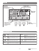
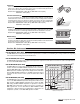
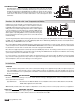
Display Item Field Displays an abbreviated name of the selected item Number Field Displays the current value of the selected item OUTDR DSGN DIFF VIEW ADJUST BOIL TARGET °F °C MIN MAX min ROOM WWSD DHW INDR UNOCC Terminal Unit Fire Delay Displays the current menu Boiler Demand DHW Demand { Status Field Displays the current status of the control’s inputs, outputs and operation Menu Field Buttons Selects Menus, Items and adjusts settings Item Symbol Description Pump Displays when the boiler pump
Sequence of Operation Section A General Operation Page 4 Section B Boiler Reset Page 5-8 Section C DHW Page 8-10 Section A —General Operation POWERING UP THE CONTROL When the Boiler Control 260 is powered up, the control displays the control type number in the LCD for 2 seconds. Next, the software version is displayed for 2 seconds. Finally, the control enters into the normal operating mode and the LCD defaults to displaying the current outdoor air temperature.
Section B: Boiler Reset Section B1 General Section B2 Installer Section B3 Advanced Section B1: General BOILER DEMAND A boiler demand is required in order for the 260 to provide heat to the heating system. A boiler demand is generated by applying a voltage between 24 and 240 V (ac) across the Boiler Demand terminals (1 and 2). Once voltage is applied, the Boiler Demand pointer is displayed in the LCD. If the 260 is not in WWSD, the 260 closes the Boil P1 contact.
Section B2: Installer OUTDOOR DESIGN (OUTDR DSGN) The OUTDR DSGN is the outdoor air temperature that is the typical coldest temperature of the year where the building is located. This temperature is used when doing the heat loss calculations for the building. If a cold outdoor design temperature is selected, the boiler supply temperature rises gradually as the outdoor temperature drops.
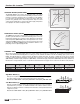
Fancoil (3) A fancoil terminal unit or air handling unit (AHU) consists of a hydronic heating coil and either a fan or blower. Air is forced across the coil at a constant velocity by the fan or blower, and is then delivered into the building space. Default values: BOIL DSGN = 190°F (88°C), BOIL MAX = 210°F (99°C), BOIL MIN = 140°F (60°C) Fin–tube Convector (4) A convector terminal unit is made up of a heating element with fins on it.
FIRE DELAY (FIRE DELAY) The Fire Delay is the delay time that occurs between the time that the 260 closes the Boiler contact and the burner fires. This delay is usually the result of burner pre-purge, or other forms of time delay built into the burner’s safety circuits. BOILER DIFFERENTIAL (BOIL DIFF) An on / off heat source such as a boiler, must be operated with a differential in order to prevent short cycling. With the 260, either a fixed or an auto differential may be selected.
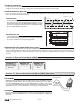
DHW Pump (DIP switch = DHW Pump) Pump If DHW Pump is selected, the 260 assumes that the DHW pump provides adequate flow through both the DHW tank heat exchanger, and the boiler. To provide heat to the DHW tank, the 260 closes the DHW Pmp / Vlv contact (9 and 10) and operates the boiler to provide a sufficient boiler supply temperature to the DHW tank. If using a primary loop with the DHW tank piped in primary / secondary, set the DIP switch to DHW Valve.
DHW MIXING PURGE After DHW priority operation, the boiler is extremely hot. At the same time, the heating zones may have cooled off considerably after being off for a period of time. To avoid thermally shocking the boiler after DHW priority, the 260 shuts off the boiler, but continues to operate the DHW while restarting the heating system. This allows some of the DHW return water to mix with the cool return water from the zones and temper the boiler return water.
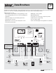
STEP THREE ROUGH-IN WIRING All electrical wiring terminates in the control base wiring chamber. The base has standard 7/8” (22 mm) knockouts which accept common wiring hardware and conduit fittings. Before removing the knockouts, check the wiring diagram and select those sections of the chamber with common voltages. Do not allow the wiring to cross between sections, as the wires will interfere with safety dividers which should be installed at a later time.
DHW Pump / Valve Contact 9 10 DHW Pmp/Vlv The DHW Pmp / Vlv terminals (9 and 10) are an isolated output in the 260. There is no power available on these terminals from the control. These terminals are to be used as a switch to either make or break power to the DHW pump or DHW valve. Since this is an isolated contact, it may switch a voltage between 24 V (ac) and 240 V (ac). or M 24 to 240 V (ac) Boiler Contact The Boiler terminals (11 and 12) are an isolated output in the 260.
Test The Sensors In order to test the sensors, the actual temperature at each sensor location must be measured. A good quality digital thermometer with a surface temperature probe is recommended for ease of use and accuracy. Where a digital thermometer is not available, a spare sensor can be strapped alongside the one to be tested, and the readings compared. Test the sensors according to the instructions in the Data Brochure D 070.
Boiler If the boiler circuit is connected to the Boiler terminals (11 and 12), make sure power to the boiler circuit is off and install a jumper between the terminals. When the boiler circuit is powered up, the boiler should fire. If the boiler does not turn on, refer to any installation or troubleshooting information supplied with the boiler. (The boiler may have a flow switch that prevents firing until the boiler pump (P1) is running).
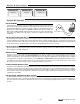
ADJUST °F ROOM UNOCC Press and release the Item button to advance to the ROOM UNOCC adjustment. Use the or button to set the desired temperature. The ROOM UNOCC setting is set to the desired room air temperature during the unoccupied (Night) mode. Note: To increase or decrease space temperature during the unoccupied (Night) mode, only adjust the ROOM UNOCC setting. OUTDR DSGN ADJUST °F Press and release the Item button to advance to the OUTDR DSGN adjustment.
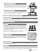
Se ct i In on st a Ad ller va nc ed Adjust Menu (1 of 2) Display ADJUST °F ROOM The desired room air temperature during an occupied (Day) period. 35 to 100°F (2 to 38°C) B2 The desired room air temperature during an unoccupied (Night) period. 35 to 100°F (2 to 38°C) B2 The design outdoor air temperature used in the heat loss calculation for the heating system.
Se ct i In on st a Ad ller va nc ed Adjust Menu (2 of 2) Display ADJUST °F B3 WWSD UNOCC ADJUST °F Description Range The system’s warm weather shut down during the unoccupied (Night) period. 35 to 100°F, OFF (2 to 38°C, OFF) The units of measurement that all of the temperatures are to be displayed in the control. °F, °C Actual Setting ADJUST This item exits the ADJUST menu by pressing either the or button.
Troubleshooting When troubleshooting any heating system, it is always a good idea to establish a set routine to follow. By following a consistent routine, many hours of potential headaches can be avoided. Below is an example of a sequence that can be used when diagnosing or troubleshooting problems in a hydronic heating system. Establish the Problem Establish the problem. Get as much information from the customer as possible about the problem.
Error Messages VIEW The control was unable to read a piece of information from its EEPROM. This error can be caused by a noisy power source. The control will load the factory defaults and stop operation until all the settings are verified. VIEW This error is caused by an illegal DHW DIP switch setting. When DHW Priority and DHW Valve are selected in the DIP switch settings, the control will flash the error message.
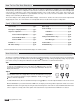
Technical Data Boiler Control 260 One Stage Boiler & DHW Optional devices — — — — — — — — — — D 260, A 260’s, D 001, D 070, E 003. Microprocessor PID control; This is not a safety (limit) control. 3.0 lb. (1340 g), Enclosure A, blue PVC plastic 6-5/8” H x 7-9/16” W x 2-13/16” D (170 x 193 x 72 mm) CSA C US, CSA 22.2 No 24 and UL 873, meets class B: ICES & FCC Part 15. Indoor use only, 32 to 113°F (0 to 45°C), < 90% RH non-condensing.