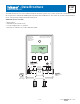
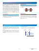
- Data Brochure D 257 DHW Control 257 03/09 The DHW Control 257 is used for dedicated domestic hot water systems. The control operates two on/off boilers, or one two-stage boiler to maintain the DHW Target temperature at the DHW Sensor. The control can operate in Proportional (P) mode, or Proportional, Integral, Derivative (PID) mode.
How to Use the Data Brochure This brochure is organized into three main sections. They are: 1) Sequence of Operation, 2) Installation, and 3) Control Settings. The Control Settings section of this brochure describes the various items that are adjusted and displayed by the control. The control functions of each adjustable item are described in the Sequence of Operation. Table of Contents User Interface ............................................................... 2 Display and Symbol Description.........
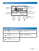
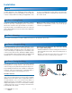
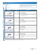
Display Number Field Menu Field Displays the current value of the selected item Displays the current menu Status Field Item Field Displays the current item selected. Stage Mode Delay DHW Differential Target DHW Displays the current status of the control’s inputs, outputs and operation Buttons Selects Menus, Items and adjusts settings Item Symbol Description ▼ POINTER Displays the control operation as indicated by the text.
Sequence of Operation Powering Up the Control When the DHW Control 257 is powered up all LCD segments are displayed for 2 seconds followed by the version number being displayed for 2 seconds. The control then enters into the normal operating mode and the LCD defaults to displaying the current DHW temperature.
Rotation This function rotates the firing sequence of the two boilers based on the accumulated running hours of each stage. The HEAT 1 and HEAT 2 items in the default menu display the accumulated running hours of each stage. When one stage has accumulated 48 hours more running hours than the other stage, the operating sequence is rotated. The stage with less running hours is rotated in the firing sequence to turn on first, while the stage with more running hours will turn on last.
Installation Caution Improper installation and operation of this control could result in damage to the equipment and possibly even personal injury. It is your responsibility to ensure that this control is safely installed according to all applicable codes and standards. This electronic control is not intended for use as a primary limit control. Other controls that are intended and certified as safety limits must be placed into the control circuit.
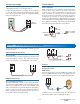
Test the Power Supply Test the Outputs Make sure exposed wires and bare terminals are not in contact with other wires or grounded surfaces. Heat 1 and Heat 2 Make sure power is off to the boiler circuits and connect the TT contacts on the boilers to the Heat 1 and Heat 2 contacts on the control. Install jumpers at the Heat 1 and Heat 2 terminals to externally close the switch. When the boiler circuits are powered up, the boilers should fire.
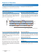
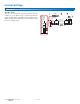
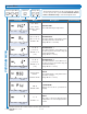
Control Settings DIP Switch Settings On Off © 2009 D 257 - 03/09 8 of 12 DHW Control 257 Rotate On 1 Po C Off Date Code Item Rotate Off | On - Rotate The Off | On – Rotate DIP switch is used to turn boiler rotation on or off. When using a single boiler with two stages, the DIP switch should be in the off (down) position. When using two single-stage boilers, the DIP switch should be in the on (up) position.
Default Menu View Next Item The Default menu items display current operating temperatures and system status information. Use the Item button to view items in this menu. Item Item Field Range Description DHW TEMPERATURE The current DHW temperature as measured by the DHW sensor. HEAT is displayed with a 1 or 2 when either the Heat 1 or Heat 2 relay is closed.
Program Menu Enter Program Menu Next Item Item Change Value Item Item Field The Program menu items are the programmable settings used to operate the system. Press and hold all three buttons simultaneously to enter the Program menu.
Field Test To test the control, push and hold the up button for 3 seconds while in the default menu. While in Field Test “tSt” is displayed. Step 1: Heat 1 relay will close and Heat 2 relay will open for 10 seconds Step 2: If rotate switch is off, both Heat 1 and Heat 2 relays will close for 10 seconds. If rotate switch is on, Heat 1 relay will open and Heat 2 relay will close for 10 seconds. Stage Mode Step 3: The test routine ends and the control resumes normal operation.
Technical Data DHW Control 257 Two Stage Ambient conditions Power supply Relay Sensors included: optional: — — — — — — Power: 24 V ±10% 50/60 Hz 3 VA Relays: 240 V (ac) 10 A 1/3 hp Meets Class B: Canadian ICES FCC Part 15 Made in Canada tektra 906-11 H3014B D 257, A 257, D 001, D 070 Microprocessor control; This is not a safety (limit) control 0.78 lb. (355 g) Enclosure C, White PVC Plastic 4-3/4” H x 2-7/8” W x 7/8” D (120 x 74 x 22 mm) CSA C US, CSA 22.