- Installation & Operation Manual D 256 Boiler Control 256 07/11 The Boiler Control 256 is designed to control a single stage heat source in order to provide outdoor reset. The control has a Liquid Crystal Display (LCD) to view system status and operating information.
How to Use the Data Brochure This brochure is organized into four main sections. They are: 1) Sequence of Operation, 2) Installation, 3) Control Settings, and 4) Troubleshooting. The Sequence of Operation section has three sub-sections. We recommend reading Section A: General Operation of the Sequence of Operation, as this contains important information on the overall operation of the control. Then read the sub-sections that apply to your installation.
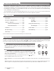
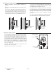
Display Item Field Displays an abbreviated name of the selected item Number Field Displays the current value of the selected item OUTDR DSGN DIFF BOIL TARGET MINMAX ROOM WWSD INDR UNOCC VIEW ADJUST °F °C Displays the current menu Boiler Demand Terminal Unit { Status Field Displays the current status of the control’s inputs, outputs and operation Menu Field Buttons Selects Menus, Items and adjusts settings Item Symbol Description Burner Displays when the boiler relay is turned on.
Sequence of Operation Section A General Operation Page 4 Section B Boiler Reset Page 5-8 Section A — General Operation POWERING UP THE CONTROL Design Supply Terminal Unit Indoor Design Increasing Water Temperature When the Boiler Control 256 is powered up, the control displays the control type number in the LCD for 2 seconds. Next, the software version is displayed for 2 seconds.
Section B: Boiler Reset Section B1 General Section B2 Installer Section B3 Advanced Section B1: General 7 T 8 9 Power R+ C- BOILER DEMAND A boiler demand is required in order for the 256 to provide heat to the heating system. A boiler demand is generated by connecting terminal T(7) to terminal C-(9) through a switching device. Once the switching device closes, the Boiler Demand pointer is displayed in the LCD.
ROOM OCC & UNOCC (ROOM) The ROOM is the desired room temperature for the boiler zones, and it provides a parallel shift of the Characterized Heating Curve. The room temperature desired by the occupants is often different from the design indoor temperature (BOIL INDR). If the room temperature is not correct, adjusting the ROOM setting increases or decreases the amount of heat available to the building. A ROOM setting is available for both the occupied (Day) and unoccupied (Night) modes.
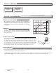
Radiator (5) A radiator terminal unit has a large heated surface that is exposed to the room. A radiator provides heat to the room through radiant heat transfer and natural convection. Default values: BOIL DSGN = 160°F (71°C), BOIL MIN = 140°F (60°C) Baseboard (6) A baseboard terminal unit is similar to a radiator, but has a low profile and is installed at the base of the wall. The proportion of heat transferred by radiation from a baseboard is greater than that from a fin-tube convector.
BOILER DIFFERENTIAL (BOIL DIFF) An on / off heat source such as a boiler, must be operated with a differential in order to prevent short cycling. With the 256, either a fixed or an auto differential may be selected. on Bo i le r Boi ler on off iler Bo off 160°F (71°C) ile r The boiler differential is divided around the BOIL TARGET temperature.
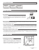
STEP TWO CONTROL INSTALLATION Enclosure C -------------------------------------------------------Enclosure C is designed for smaller controls and their wiring. This enclosure has either a large or a small window opening depending on the control used. Mounting the C Enclosure -----------------------------------------Grasp the front cover by the fingertip grips on the top and bottom of the enclosure and pull the front cover off. Remove the wiring cover screw.
Mounting the Outdoor Sensor Note: The temperature sensor (thermistor) is built into the enclosure. In order to prevent heat transmitted through the wall from affecting the sensor reading, it may be necessary to install an insulating barrier behind the enclosure. Remove the screw and pull the front cover off the sensor enclosure.
Mounting the Universal Sensor Note: This sensor is designed to mount on a pipe or in a temperature immersion well. The Universal Sensor should be placed downstream of a pump or after an elbow or similar fitting. This is especially important if large diameter pipes are used as the thermal stratification within the pipe can result in erroneous sensor readings. Proper sensor location requires that the fluid is thoroughly mixed within the pipe before it reaches the sensor.
STEP FOUR TESTING THE WIRING No wires should be connected to the control during the testing. The following tests are to be performed using standard testing practices and procedures, and should only be carried out by properly trained and experienced persons. A good quality electrical test meter, capable of reading from at least 0 - 300 V (ac) and at least 0 - 2,000,000 Ohms, is essential to properly test the wiring and sensors.
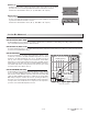
Test The Power Supply Make sure exposed wires and bare terminals are not in contact with other wires or grounded surfaces. Turn on the power and measure the voltage across the 24 V (ac) power supply with an AC voltmeter. The reading should be between 22 and 26 V (ac). V Ω V Class 2 Transformer C R 24 V (ac) Test The Powered Inputs Boiler Demand Measure the voltage between the boiler demand wire and the power wire that goes to R+ of the control.
STEP FIVE ELECTRICAL CONNECTIONS TO THE CONTROL The installer should test to confirm that no voltage is present at any of the wires. 8 9 Power R+ C- Powered Input Connections 24 V (ac) Power Connect the 24 V (ac) power supply to the Power R+ and Power C- terminals (8 and 9). This connection provides power to the microprocessor and display of the control.
DIP Switch Setting Inst/Adv ADVANCED / INSTALLER The Advanced / Installer DIP switch is used to select which items are available to be viewed and / or adjusted in the user interface. Do not apply power 1 2 3 4 Boi l Out Com UnO Sw Quick Setup To enter the Installer programming mode, set the Advanced / Installer DIP switch to Installer. Access the ADJUST menu by pressing and holding simultaneously for 1 second, all 3 buttons. The display will now show the word ADJUST in the top right corner.
Se ct i In on st a Ad ller va nc ed View Menu (1 of 1) Display OUTDR Description Range VIEW °F Current outdoor air temperature as measured by the outdoor sensor. This is also the default display for the control. OCC -67 to 149°F (-55 to 65°C) VIEW °F BOIL B3 Current boiler supply water temperature as measured by the boiler sensor. 14 to 266°F (-10 to 130°C) B1 B3 Target boiler supply is the temperature the control is currently trying to maintain at the boiler sensor.
Se ct i In on st a Ad ller va nc ed Adjust Menu (2 of 2) Display ADJUST °F BOIL MIN DIFF Description Range B3 The minimum temperature allowed for the boiler target temperature. OFF, 80 to 180°F (OFF, 27 to 82°C) B3 The differential that the control is to use when it is operating the boiler. Ad, 2 to 42°F (Ad, -17 to 6°C) B3 The system’s warm weather shut down during the occupied (Day) period.
Testing the Control The Boiler Control 256 has a built-in test routine which is used to test the boiler function. The 256 continually monitors the sensors, and displays an error message whenever a fault is found. See the following pages for a list of the 256’s error messages and possible causes. When the button is pressed, the Boiler relay closes and the control displays the burner segment. Once the button is released, the Boiler relay returns to normal operation.
Error Messages VIEW OUTDR VIEW OUTDR VIEW The control was unable to read a piece of information from its EEPROM. This error can be caused by a noisy power source. The control will load the factory defaults and stop operation until all the settings are verified. The control is no longer able to read the outdoor sensor due to a short circuit. In this case, the control assumes an outdoor temperature of 32°F (0°C) and continues operation. Locate and repair the problem as described in the Testing section.
Technical Data D256, A256 Control Microprocessor control. This is not a safety (limit) control Packaged weight Dimensions Enclosure Approvals Ambient conditions 1.3 lb. (580 g) 4-3/4” H x 2-7/8” W x 7/8” D (120 x 74 x 22 mm) White PVC plastic, Nema Type 1 CSA C US, meets class B: ICES & FCC Part 15 Indoor use only, 32 to 104°F (0 to 40°C), RH ≤90% Non-condensing Press & Release: all 3 buttons, to adjust menu Power: Press & Hold: Item, to view settings , to test.