
Application Brochure


Product design, software and literature are Copyright © 2000 by:
tekmar Control Systems Ltd. and tekmar Control Systems, Inc.
System Operation
All specifications are subject to change without notice.
2 of 8
tekmar Control Systems Ltd., Canada
tekmar Control Systems, Inc., U.S.A.
Head Office: 5100 Silver Star Road
Vernon, B.C. Canada V1B 3K4
Tel. (250) 545-7749 Fax. (250) 545-0650
Web Site: www.tekmarcontrols.com
Control Systems
A 256-1 05/00
Printed in Canada. A 256-1 05/00.
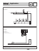
The Boiler Control 256 provides partial or full outdoor reset to four (or more) thermostatic radiator valve zones. Constant circulation to
the system is provided by the boiler pump (P1). The boiler operates at the required temperature in order to satisfy the load.
Heat Source Details The heat source can be either a high mass or low mass non-condensing or low temperature boiler.
Piping Details Thermostatic radiator valve (TRV) zones are piped into the boiler loop. A pressure differential valve (V1) provides a
bypass for the boiler pump (P1) in the event that most of the TRV’s are closed.
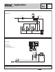
Boiler Demand The boiler supply water temperature is based on the
Characterized Heating Curve
settings. The boiler is fired to satisfy
the required boiler supply water temperature. Whenever the boiler is fired, the 256 aims to increase the boiler supply water temperature
to at least the BOIL MIN setting. In this application the control requires a permanent heat demand. A permanent heat demand is
generated by wiring the
C-
(9) side of the transformer to
T
(7).
All control functions and specifications are listed in the Product Catalog I 000 and Data Brochure D 256.