
Application Brochure

A 152-4
In North America: tekmar Control Systems Ltd., Canada
tekmar Control Systems, Inc., U.S.A.
Head Office: 4611 - 23rd Street
Vernon, B.C. Canada V1T 4K7
Tel. (604) 545-7749 Fax. (604) 545-0650
All specifications are subject to change without notice.
Printed in Canada on recycled paper.
Product design, software and literature are Copyright © 1993 by:
tekmar Control Systems Ltd. and tekmar Control Systems, Inc.
Printed in Canada on recycled paper by
Wayside Press Ltd. Vernon / Kelowna, B.C.
2
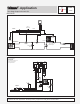
Operation
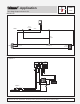
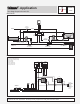
The Two Stage Setpoint Control 152 maintains a separate setpoint temperature for each of two independant heating systems in a
single area. Setpoint 1 uses the reading from its Slab Sensor 072 or 073 to maintain the slab at a fixed temperature setting. Setpoint 1
should be set lower than the desired air temperature, or air conditioning may be required in milder weather.
Setpoint 2 uses the reading from its Indoor Sensor 074 to operate the fan coil; providing fast air temperature recovery when required.
Setpoint 2 should be set at the desired air temperature.
The following are minimum recommended specifications for the control in this application.
•The 2-way injection zone valve shall be closed if the HRF zone slab temperature increases above the Setpoint 1 setting.
•The fan coil pump and fan motor shall operate when the room's air temperature drops below the Setpoint 2 setting (room air
temperature).
•The boiler shall operate on its own controls to maintain a temperature warm enough to ensure that the air temperature leaving
the fan coil is at least 90°F (32°C) when operating.
•The control shall have an adjustable setpoint, differential and on time delay for each stage.
•The control must be compatible with standard North American wiring hardware.
• The control shall be microprocessor-based and have two SPST internal relays with 10 amp (resistive) isolated contacts for outputs.
• The control shall be able to display the setpoint, differential and delay for either stage while the device is operating.
• The installation location must be maintained within the ambient temperature and humidity ranges specified in the D 152 Brochure
for this control, with the installer ensuring that the control and its wiring are isolated and/or shielded from strong sources of
electromagnetic noise.
• The control shall continuously monitor its sensors and provide an error message upon sensor or wiring failure.
• The control components required from tekmar are a Two Stage Setpoint Control 152, Slab Sensor 072 or 073, an Indoor
Sensor 074and one Relay 003. (The Supply Sensor 071 included with this control should not be used if the sensor is to be poured
directly into a concrete slab without using conduit).
Specifications
Two Stage Setpoint Control 152 Adjustment Range Recommended Initial Setting
Temperature Display -85 to 302°F (-65 to 150°C)
Setpoint 1 -40 to 239°F (-40 to 115°C)
Differential 1 1 to 40°F (1 to 22°C)
Time Delay 1 0 to 19 min. 50 sec.
(10 second increments)
Operating Mode 1 Heating/Cooling Heat
Setpoint 2 -40 to 239°F (-40 to 115°C)
Differential 2 1 to 40°F (1 to 22°C)
Time Delay 2 0 to 19 min. 50 sec.
(10 second increments)
Operating Mode 2 Heating/Cooling Heat
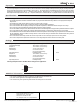
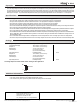
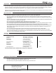
Settings
Two Stage Setpoint Control 152 DIP switch setting for this application.
Additional Information
•For control installation and testing instructions see Brochures D 001 and D 152.
•For other control applications see Application Register A 000.
•For control theory and system integration details see Essays E 001 and E 002.
On
1
Off
2 Sensors