
Application Brochure
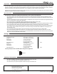

Electrical
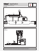
Mechanical
- Application
Note:
This is only a concept drawing. Designers must determine whether this system will work in each application and must ensure
compliance with code requirements. Necessary auxiliary equipment and safety devices must be added.
Two Stage Setpoint Control 152
A 152-2
12/93
3
4
6
5
7
2
1
8
3
4
6
5
7
2
1
8
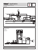
24Vac
120Vac
C
R
N
L
12
3
4 56789
C
Power
R
Relay 1
Com
Sen
S1
Sen
S2
Sen
Relay 2
152
24V only
No Power
S1
S2
To boiler
control circuit
or Setpoint
Demand
signal for
tekmar boiler
control
(requires
24Vac)
P2
P3
P5P4
R1
R2
Class II
Transformer
120Vac
24Vac
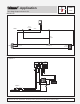
System Pump (P1)
Spa
Pump (P5)
Spa Sensor
(S2) 071
Pool Heat Exchanger
Pump (P3)
Relay
R1 003
Relay
R2 003
Pool
Pump (P4)
Pool
Sensor
(S1) 071
to other
heating zones
Pool
Spa
152
Spa Heat
Exchanger
Pump (P2)
Max. 4 pipe
diameters apart
Max. 4 pipe
diameters apart
10A 10A
P1 = System Pump
P2 = Spa Heat Exchanger Pump
P3 = Pool Heat Exchanger Pump
P4 = Pool Pump
P5 = Spa Pump
R1, R2 = Relays 003
S1 = Pool Sensor 071
S2 = Spa Sensor 071
On
—
Off
Class II
Transformer