
Application Brochure

One Stage Setpoint Control 150
Literature — A 150's, D 150, D 001, D 070
Control — Microprocessor control; This is not a safety (limit) control.
Packaged weight — 0.7 lb. (330 g), Enclosure C, PVC plastic
Dimensions — 4-3/4” H x 2-7/8” W x 7/8” D (120 x 74 x 22 mm)
Approvals — CSA C US, CSA 22.2 No 24 and UL 873, meets class B: ICES & FCC Part 15
Ambient conditions — Indoor use only, -20 to 120°F (-30 to 50°C), < 90% RH non-condensing.
Power supply —
24 V (ac) ±10%, 50/60 Hz, 1.3 VA or 24 V (dc) ± 10% 0.02 A
Relays — 240 V (ac) 8 A, 1/4 hp
Sensors — NTC thermistor, 10 kΩ @ 77°F (25°C ±0.2°C) ß=3892
included: Universal Sensor 071.
Programmed settings — Ten year memory backup
Control accuracy — ±0.5°F (±0.3°C) with up to 500 feet (150 m) of 18 AWG wire to sensors.
Temperature display
— -85 to 302°F (-65 to 150°C)
Setpoint
— -40 to 239°F (-40 to 115°C)
Differential (Bang/Bang) — 1 to 40°F (1 to 22°C)
Differential (PWM)
— 3 to 40°F (2 to 22°C)
Time Delay (Bang/Bang) — 0 to 19 min. 50 sec.
Cycle Length(PWM)
— 30 sec. to 19 min. 50 sec.
Operating mode
— Heating / Cooling
Temperature display
— Fahrenheit / Celsius
System Operation & Specifications
Technical Data
A 150-2
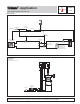
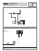
The One Stage Setpoint Control 150 is used to enable a boiler in a pool heating system. The boiler is enabled using a Pulse Width
Modulation control logic. The boiler water temperature is controlled by the boiler's operating aquastat.
Piping and Heat Source Details The boiler loop and the pool loop are isolated from each other through the use of a heat exchanger.
The boiler loop pump (P1) is run by the boiler control and provides flow through the boiler side of the heat exchanger whenever the
boiler is enabled. The pool loop pump (P2) operates continuously and circulates a portion of the pool water through the pool side of
the heat exchanger according to the set up of the balancing valve (V1).
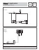
Setpoint Operation The 150 enables the boiler based on a Pulse Width Modulation logic. Once the 150 is powered up, the installer /
operator is required to set the
Setpoint
,
Differential
and
Cycle
settings on the 150. The 150 will monitor the pool return temperature
using the Universal Sensor 071 (S1) and will use this information in conjunction with the user input settings to enable the boiler. For a
description of Pulse Width Modulation, refer to Data Brochure D 150.
Additional Functions Additional control functions are listed in the table in the Setpoint Controls section of the Product Catalog I 000.
Note: For optimum system operation, high thermal mass systems such as pools should use the Pulse Width Modulation mode of
operation. Low thermal mass systems such as hot tubs and spas should use the On / Off Differential mode of operation.
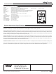
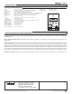
One Stage Setpoint
Control 150
C-
Sensor
Setpoint
Differential
Delay/Cycle
PRGM
HEAT COOL
FC
Item
R+
Com
5
N/C
PWM
On
Off
6
7
Power
12
3
4
N/O
Meets Class B:
Canadian ICES
FCC Part 15
Made in Canada
H1094G
tektra 905-01
Power 24 V (ac) ± 10% 50/60 Hz 1.3 VA
24 V (dc) ± 10% 0.02 A
Relay 240 V (ac) 8 A 1/4 hp
No Power
Signal wiring must be
Date Code
rated at least 300 V
Made in Canada
tekmar Control Systems Ltd., Canada
tekmar Control Systems, Inc., U.S.A.
Head Office: 5100 Silver Star Road
Vernon, B.C. Canada V1B 3K4
Tel. (250) 545-7749 Fax. (250) 545-0650
Product design, software and literature are Copyright © 2008 by:
tekmar Control Systems Ltd. and tekmar Control Systems, Inc.
Printed in Canada on recycled paper by
Control Systems
All specifications are subject to change without notice.
Printed in Canada. A 150-2 - 12/08