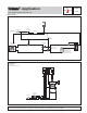
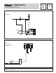
- Application A 150-1 12/08 One Stage Setpoint Control 150 Mechanical 150 On/Off Switch Class 2 Transformer 24 V (ac) 120 V (ac) Relay (R1) 003 Balancing Valve Slab Sensor (S1) 072 or 073 Slab Pump (P1) Boiler Pump Max. 4 pipe diameters apart Storage Tank for thermal mass —may be required if low mass boiler is used.
A 150-1 Operation The One Stage Setpoint Control 150 regulates the temperature of the slab by turning the injection pump on and off in response to temperature changes at the slab sensor. Note: For optimum control, the supply temperature from the boiler should be constant. This will allow the system to be balanced so that the supply fluid to the slab is just hot enough to maintain the slab temperature at design conditions.
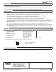
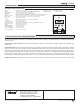
- Application A 150-2 12/08 One Stage Setpoint Control 150 Mechanical 150 Class 2 Transformer 24 V (ac) 120 V (ac) Pool Sensor (S1) 071 P2 PWM Electrical P1 = Boiler Pump P2 = Pool Pump S1 = Pool Sensor 071 V1 = Balancing Valve or Globe Valve P1 V1 150 8A 1 2 3 4 On — Power Off C- R+ Com N/O 8A No Power 5 6 7 N/C Sensor High Mass Low Mass - S1 Boiler Class 2 Transformer 24 V (ac) C 120 V (ac) L P2 R N Note: This is only a concept drawing.
A 150-2 Technical Data One Stage Setpoint Control 150 — — — — — — — — — — — — — — — — — Operating mode A 150's, D 150, D 001, D 070 Temperature display Microprocessor control; This is not a safety (limit) control. 0.7 lb. (330 g), Enclosure C, PVC plastic 4-3/4” H x 2-7/8” W x 7/8” D (120 x 74 x 22 mm) CSA C US, CSA 22.2 No 24 and UL 873, meets class B: ICES & FCC Part 15 Indoor use only, -20 to 120°F (-30 to 50°C), < 90% RH non-condensing. 24 V (ac) ±10%, 50/60 Hz, 1.3 VA or 24 V (dc) ± 10% 0.
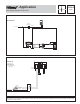
- Application A 150-3 12/08 One Stage Setpoint Control 150 Mechanical 150 Class 2 Transformer 24 V (ac) 120 V (ac) DHW Recirculation Loop DHW Sensor (S1) 071 P1 A1 P2 PWM Electrical Domestic Cold Water A1 = DHW High Limit Aquastat P1 = Boiler Pump P2 = DHW Recirculating Pump S1 = DHW Sensor 071 150 8A 8A 1 2 3 4 No Power 5 6 7 On — Power Off C- R+ Com N/O N/C Sensor A1 S1 Boiler Class 2 Transformer 24 V (ac) C 120 V (ac) L P2 R N Note: This is only a concept drawing.
A 150-3 Technical Data One Stage Setpoint Control 150 — — — — — — — — — — — — — — — — — Operating mode A 150's, D 150, D 001, D 070 Temperature display Microprocessor control; This is not a safety (limit) control. 0.7 lb. (330 g), Enclosure C, PVC plastic 4-3/4” H x 2-7/8” W x 7/8” D (120 x 74 x 22 mm) CSA C US, CSA 22.2 No 24 and UL 873, meets class B: ICES & FCC Part 15 Indoor use only, -20 to 120°F (-30 to 50°C), < 90% RH non-condensing. 24 V (ac) ±10%, 50/60 Hz, 1.3 VA or 24 V (dc) ± 10% 0.