
Install Instructions

© 2009 D 090 - 07/09 6 of 8
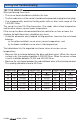
Temperature Resistance
°F °C
-49 -45 472,000
-40 -40 337,000
-31 -35 243,000
-22 -30 177,000
-13 -25 130,000
-4 -20 97,000
Temperature Resistance
°F °C
5-1572,900
14 -10 55,300
23 -5 42,300
32 0 32,600
41 5 25,400
50 10 19,900
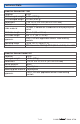
Temperature Resistance
°F °C
59 15 15,700
68 20 12,500
77 25 10,000
86 30 8,060
95 35 6,530
104 40 5,330
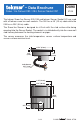
Testing and Troubleshooting
TEST THE SENSOR
When performing these tests:
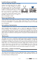
The sensor head should be installed in the slab.
The five cable wires at the control should be disconnected (unplug terminal plug).
Use a good quality electrical testing meter with an ohm scale range of 0 to
2,000,000 Ohms.
The sensor has two 10k Ohm thermistors. One reads slab surface temperature,
and the other checks sensor heater temperature.
If the sensor has been disconnected from the control for an hour or more, the
readings for both thermistors should be very close.
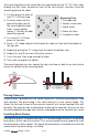
Using the ohmmeter and standard testing practices, measure the resistance
between:
(a) the yellow and black sensor wires (sensor temperature), and
(b) the brown and black sensor wires (slab temperature).
The table below lists the expected resistance values at various sensor
temperatures.
Measure the resistance between the blue and black wires. When the sensor
surface is dry, the reading should be 2,000,000 Ohms. When the sensor surface
is wet it should be between 10,000 and 300,000 Ohms.
Measure the resistance between the red and black wires of the heating element.
This reading should be close to 50 Ohms.
•
•
•
•
•
•