Fieldware SA for the Legacy 6000 Software Version 2.00 LEGACY 6000 Stand Alone USER GUIDE Software Version 2.00 98-05061 R0 Midwest Technologies 2864 Old Rochester Road Springfield, IL 62703 217.753.8424 www.mid-tech.com www.teejet.
Fieldware SA for the Legacy 6000 Software Version 2.00 Table of Contents Chapter 1 - System Introduction ...................................................................................... 1-1 System Introduction ...................................................................................................... 1-2 Software Options for Fieldware - SA 2.00 ................................................................ 1-4 Legacy 6000 Console...........................................................
Fieldware SA for the Legacy 6000 Software Version 2.00 No PCMCIA Card Selected ..................................................................................... 3-19 Running Product Setup ............................................................................................... 3-25 Running the Product Setup Wizard ......................................................................... 3-27 Importing Trimble ABLines ................................................................................
Fieldware SA for the Legacy 6000 Software Version 2.00 Chapter 6 - Manual Guidance .......................................................................................... 6-1 Manual Guidance Introduction .................................................................................... 6-2 Installing the Plug-in on the Console ........................................................................... 6-3 Chapter 7 - Fieldware - SA ......................................................................
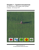
Chapter 1 - System Introduction An introduction to the Legacy 6000 System. Fieldware - SA Version 2.
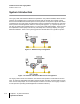
Fieldware SA for the Legacy 6000 Software Version 2.00 System Introduction The Legacy 6000, with Fieldware Stand Alone (Fieldware - SA) software installed, allows machine guidance and multiple product control when interfaced with an external rate controller. “Stand Alone” means the Mid-Tech CAN Bus product control system is not required to operate this version of Fieldware for the Legacy 6000.
Fieldware SA for the Legacy 6000 Software Version 2.00 Legacy 6000 System Features System features include: • Machine guidance without the need of a rate control system. • Where applied data collection without the need for guidance or lightbar. • Single product variable rate control when interfaced to an external rate controller. • Works with Mid-Tech's Swath XL lightbar. • Comes pre-loaded with Mid-Tech's Fieldware - SA software. • Data is stored on PCMCIA card.
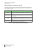
Fieldware SA for the Legacy 6000 Software Version 2.00 Software Options for Fieldware - SA 2.00 Starting with release 2.00, Fieldware - SA will be sold with three feature activations; Manual Guidance, FieldPilot and Multi Product VRT. The base software installed on the Legacy 6000 is now known as Fieldware - SA Basic. Activation Description Basic The Basic package comes with the ability to perform single product rate control, manual or variable rate (VR).
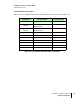
Fieldware SA for the Legacy 6000 Software Version 2.00 Compatible Rate Controllers Table 1-2 lists the compatible external rate controllers that work with this version of Fieldware - SA.
Fieldware SA for the Legacy 6000 Software Version 2.00 Legacy 6000 Console The Legacy 6000 console runs Fieldware - SA software and operates in a Windows CE environment; an extremely dependable and stable operating system. Operation is intuitive, with on-screen menu choices and prompts. An on-board help menu is built in. The heart of the Legacy console is an Intel processor operating at 206 Megahertz for maximum efficiency. Other features of the Legacy 6000 console include: Dimensions: 8.0" Wide x 7.
Fieldware SA for the Legacy 6000 Software Version 2.00 Swath XL Lightbar A CAN based Swath XL Lightbar was developed specifically for the Legacy 6000 system. The Lightbar is required for applications using guidance and recommended for non-guidance uses as well. In none guidance use (logging data only) the lightbar can provide area and rate feed back. Figure 1-3: Swath XL Lightbar Dimensions: 16.0" Wide x 3.0" High x 3.0” Deep (405 x 76 x 76 mm) Weight: 8 oz. (0.
Fieldware SA for the Legacy 6000 Software Version 2.
Chapter 2 - Getting Started Setting up Fieldware - SA for the Legacy 6000. Fieldware - SA Version 2.
Fieldware-SA for the Legacy 6000 Software Version 2.00 Software Overview This chapter assumes that the Legacy 6000 hardware has been properly installed and clean, reliable power has been supplied. Fieldware - SA Software Feature Activations Fieldware - SA software comes with several feature activations which can be configured to meet the job requirements. Each feature activation is described in Table 2-1. The actual activation of features occurs at Midwest Technologies.
Fieldware-SA for the Legacy 6000 Software Version 2.00 Powering Up To power up the Legacy 6000 console, press the orange button to the left side of the console faceplate (Figure 2-1). When the Legacy 6000 console is powered up, Fieldware - SA for the Legacy 6000 automatically starts. The first software page is the Main Fieldware - SA Launcher (Figure 22). System Setup, System Tools, and Application Rate Manager (ARM) are accessed from the Main Launcher page.
Fieldware-SA for the Legacy 6000 Software Version 2.00 Standard Pages Three basic types of software pages are used in Fieldware - SA for the Legacy 6000: a Launcher page (Figure 2-3), a Setup Menu page (Figure 2-4), and a Data Entry page (Figure 2-5). Each is described in more detail below. Each of these page types has its own help window which displays pertinent information about a button or area of the page that is highlighted.
Fieldware-SA for the Legacy 6000 Software Version 2.
Fieldware-SA for the Legacy 6000 Software Version 2.00 Setup Menu Page A Setup Menu page (Figure 2-4) is a page that contains all of the setup parameters associated with a particular setup theme, such as GPS Receiver. A Setup Menu page can be divided into three columns, Left, Center, and Right. The Left and Right columns are made up of software buttons adjacent to a physical key on the console. The center column is a scrollable list containing the name of every setup parameter and its current value.
Fieldware-SA for the Legacy 6000 Software Version 2.
Fieldware-SA for the Legacy 6000 Software Version 2.00 Data Entry Page The data entry page is used throughout Fieldware - SA software. Depending on the setup parameter being edited, a data entry page may be an alpha-numeric entry or a pick list (Figure 2-5). The data entry page is also divided into three columns: Left, Center, and Right. The left and right columns contain software buttons, typically only the back and Forward Arrow buttons. The center column is the data entry dialog box.
Fieldware-SA for the Legacy 6000 Software Version 2.00 Forward Arrow Save & Back Arrow Exit & No Save Name of Setup Parameter Setting description and help text window. Figure 2-5: Example of Pick List Data Entry Page Left most character space in the data entry dialog box.
Fieldware-SA for the Legacy 6000 Software Version 2.00 System Setup System Setup allows the configuring of the Legacy 6000 to best suit job requirements. To access the System Setup launcher, press the top left button in the Main Launcher page (Figure 2-2) (The help text should say Configure System Settings). This action brings up the System Setup Launcher page (Figure 2-7). The table below lists the current system components that can be configured.
Fieldware-SA for the Legacy 6000 Software Version 2.00 Modes of Operation In Fieldware - SA for the Legacy 6000 there are three modes of operation: Guidance Only, Log Data Only, and Application Rate control. The system is configured to operate in one of these modes during the system setup process. Guidance Only Mode The Guidance Only mode is used when only machine guidance is required. There is no rate controller in use during the guidance only operation.
Fieldware-SA for the Legacy 6000 Software Version 2.00 Setup Name Setting Description Log Data Mode without Lightbar Lightbar Off If the Lightbar is set to Off, guidance can not be used, but WhereApplied data can be logged to the PC card. The lightbar is not required. Table 2-3: Log Data and Guidance Only Mode Settings Rate Control Mode The Rate Controller mode implies that an external rate controller is connected to one of the COM ports on the Legacy 6000 console.
Fieldware-SA for the Legacy 6000 Software Version 2.00 Console Setup Console Setup defines system environment settings (units, language, time) that are displayed on the console and used in the rate control and guidance applications. To access Console Setup from the Main Launcher page (Figure 2-2), select System Setup (Figure 2-7) / Console Setup (Figure 2-8). All console setup parameters are listed in Table 2-5.
Fieldware-SA for the Legacy 6000 Software Version 2.00 Setting PC Card Units Language Description Indicates to the Legacy 6000 system that a PCMCIA data card is being used. Defines the system units; Metric or US. Defines the system language. System Date Sets the system date. Date Format Defines the date format to be displayed on the console. Settings are 12 hr. and 24 hr. System Time Sets the system time.
Fieldware-SA for the Legacy 6000 Software Version 2.00 Lightbar Setup Lightbar setup defines how the Swath XL lightbar is to be configured with the Legacy 6000 console. Lightbar setup parameters are listed in Table 2-6. To access Lightbar Setup from the Main Launcher page (Figure 2-2), select System Setup (Figure 2-7) / Lightbar Setup (Figure 2-9). To change any of the Lightbar settings, highlight the setting name listed in the center column of the Lightbar Setup page and press Enter.
Fieldware-SA for the Legacy 6000 Software Version 2.00 Setting Description Lightbar Defines the lightbar features to be used. Settings are Text/Lights, Text Only, or Off. If set to Text-only or Off it is not possible to use machine guidance. LED Brightness Display Mode Sets the brightness level of the lightbar LEDs and text window. Defines how the user interprets the row of LEDs on the lightbar.
Fieldware-SA for the Legacy 6000 Software Version 2.00 GPS Receiver Setup GPS Receiver setup defines the DGPS accuracy and how the GPS receiver communicates with the Legacy 6000 console. GPS Receiver setup parameters are listed in Table 2-7. To access GPS Setup from the Main Launcher page (Figure 2-2), select System Setup (Figure 27) / GPS Receiver Setup (Figure 2-10).
Fieldware-SA for the Legacy 6000 Software Version 2.00 Setting Description Use GPS Defines whether the Legacy 6000 system is using GPS. If using GPS, this setting must be set to Yes. Accuracy Defines the accuracy of the DGPS receiver. Choices are RTK and Sub-meter. Height Enter the height of the antenna above the ground. Com Port Defines the com port that the GPS receiver is connected to. Baud Rate Defines the selected com port baud rate.
Fieldware-SA for the Legacy 6000 Software Version 2.00 Implement Setup Implement Setup defines the spatial relationship (distance and direction) of the swath to the GPS antenna. Implement Setup is a step by step (wizard fashion) process. To access Implement Setup from the Main Launcher page (Figure 2-2), select System Setup (Figure 2-11) / Implement Setup (Figure 2-13).
Fieldware-SA for the Legacy 6000 Software Version 2.
Fieldware-SA for the Legacy 6000 Software Version 2.00 Running Implement Setup with a Rate Controller When operating Fieldware - SA with an external rate controller interfaced to the console, Implement setup is reduced to Implement width, Y-Axis Direction and Y-Axis Distance. Boom section setup is done on the rate controller connected to the Legacy console. Entering the Implement Width The first page in the Implement Setup process is the implement width (Figure 2-13).
Fieldware-SA for the Legacy 6000 Software Version 2.00 Entering the Offset Direction Y The Y direction offset is the direction, (along the center line of the vehicle) from the GPS antenna to the center of a swath (Figure 2-12). Refer to “The Vehicle Coordinate System” on page 2-19 for a description of the offset directions and distances.
Fieldware-SA for the Legacy 6000 Software Version 2.00 The Offset Distance Y When entering the Y Offset Direction, it is necessary to enter the Y Offset Distance. This is the distance from the GPS antenna, along the vehicle center line, to the swath. Refer to “The Vehicle Coordinate System” on page 2-19 for a description of the offset directions and distances. To obtain the most accurate application files and maps, we recommend that this distance be measured and not estimated or guessed.
Fieldware-SA for the Legacy 6000 Software Version 2.00 Completing Implement Setup The last Implement Setup page is the Finish page (Figure 2-16). There are two buttons on the Finish page; a Review Configuration button and a Save button. Pressing the Review configuration button displays all of the implement setup settings just entered (Figure 2-17). The Save button saves the current Implement configuration parameters to a setup file.
Fieldware-SA for the Legacy 6000 Software Version 2.00 Running Implement Setup with No Rate Controller This section describes the Implement Setup steps used when no rate controller is connected to the Legacy console and the Mid-Tech boom sense cable is being used. Boom Sense Options The Legacy 6000 has several boom sense options, a Mid-Tech three, five, or nine section Switch Box or a five or nine section Boom Sense cable.
Fieldware-SA for the Legacy 6000 Software Version 2.00 Entering the Implement Width See “Entering the Implement Width” on page 2-21. Entering the Number of Sections in a Swath The Sections page is where the number of sections in the swath is entered. The maximum number of sections is nine. When the correct number of sections is entered, press the Forward Arrow button to move to the next setup page. Swath sections are ordered left to right with respect to a forward facing vehicle.
Fieldware-SA for the Legacy 6000 Software Version 2.00 Setting the Section to Switch Assignment The Section to Switch page, allows a physical switch to be assigned to the current Swath Section. This allows individual sections to be turned on and off. This boom section activity is properly displayed in the real-time map view as well as properly recorded in the application file (.RCD). When the correct section to switch assignment is entered, press the Forward Arrow button to move to the next setup page.
Fieldware-SA for the Legacy 6000 Software Version 2.00 Entering the Section Width The Section Width page is where the width of a section is entered. When the correct section width is entered, press the Forward Arrow button to move to the next setup page. If there is more than one section for the swath, Implement setup loops through the Section to Switch Assignment and Boom Width pages for each section.
Fieldware-SA for the Legacy 6000 Software Version 2.00 Entering the Offset Direction X The Offset Direction X (Figure 2-22) is the direction, left or right, of the vehicle center line (GPS antenna), that the center of a swath is offset. Typically this is set to None, since most swaths are centered on the vehicle’s center line. Refer to “The Vehicle Coordinate System” on page 2-19 for a description of the offset directions and distances.
Fieldware-SA for the Legacy 6000 Software Version 2.00 Completing Implement Setup The last Implement Setup page is the Finish page (Figure 2-24). There are two buttons on the Finish page; a Review Configuration button and a Save button. Pressing the Review configuration button displays all of the implement setup settings just entered (Figure 2-25). The Save button saves the current Implement configuration parameters to a setup file.
Fieldware-SA for the Legacy 6000 Software Version 2.00 Controller Setup The type of external rate controller to be connected to the Legacy 6000 console is selected in Controller Setup. A complete list of compatible external rate controllers can be found in Table 2-9. To access Controller Setup from the Main Launcher page (Figure 2-2), select System Setup (Figure 2-11) / Controller Setup (Figure 2-26). Figure 2-26: The Controller Setup Page All Controller Setup parameters are listed in Table 2-8.
Fieldware-SA for the Legacy 6000 Software Version 2.00 Compatible Rate Controllers Table 2-9 lists the compatible external rate controllers that work with this version of Fieldware - SA.
Fieldware-SA for the Legacy 6000 Software Version 2.00 Backing up System Files This completes the System Setup process for Fieldware - SA for the Legacy 6000 console. It is important to backup the system files to the PC card as soon as System Setup is completed. For more information on backing up the system configuration see “The Device Manager” on page 2-36 (Table 2-11).
Fieldware-SA for the Legacy 6000 Software Version 2.00 System Tools System Tools allows some basic system diagnostics to be performed. System Tools is accessed from the Main Launcher page (Figure 2-27). To access the System Tools launcher, press the Tools button in the Main Launcher page (the help text should say View System Tools). This action brings up the System Tools launcher page (Figure 2-28). Table 2-10 below lists the current System Tools.
Fieldware-SA for the Legacy 6000 Software Version 2.00 Tool Device Manager Card Manager Description This tool allows the viewing of all components on the Legacy system including the Mid-Tech CAN Bus, external rate controller, and GPS receiver. This application runs in conjunction with the PC card. The card must be inserted to run this application. Card manager allows basic file manipulation.
Fieldware-SA for the Legacy 6000 Software Version 2.00 The Device Manager This tool allows the viewing of all components connected to the Mid-Tech Legacy 6000 system. In Fieldware - SA, the GPS Receiver, Rate Controller, Console, and Lightbar are available for diagnostics. To access the Device Manager diagnostic page from the Main Launcher page, select System Tools (Figure 2-28) / Device Manager (Figure 2-29). Scroll through all of the connected devices and review the current status of these devices.
Fieldware-SA for the Legacy 6000 Software Version 2.
Fieldware-SA for the Legacy 6000 Software Version 2.00 Console When selecting Console as the device for diagnostics, a Console Information page is displayed, listing the console serial number and version number (Figure 2-31). Figure 2-31: The Console Information Page Button Description System File Backup. Press this button and the console system files are backed up to the PC card. Update Console System Files. Press this button to update the console system files with system files located on the PC card.
Fieldware-SA for the Legacy 6000 Software Version 2.00 The Plug-Ins activated can be reviewed from the Console Information page. Backing up Console System Files The Legacy 6000 (L6K) system files can be backed up to a PC card. This allows the system to be restored at a later date or transferred to another L6K console if necessary. Required Items: • 20 Meg (or larger) ATA Flash PC Card CAUTION: Always make sure that the console is powered off before inserting or removing the PC card.
Fieldware-SA for the Legacy 6000 Software Version 2.00 Importing Object Name Files into Console Memory Fieldware - SA allows Object Name Files to be imported. An Object Name File is a simple text file that contains a list of Point and Hazard object names that are commonly used during product application and mapping. Using an Object Name file helps to efficiently store, select, and name mapping objects while out in the field.
Fieldware-SA for the Legacy 6000 Software Version 2.00 GPS Receiver This tool allows the viewing of any GPS data coming into the com port on the Legacy 6000. It is recommended this diagnostic be run the first time the GPS receiver is connected to the Legacy 6000 console. To access the GPS Receiver diagnostic page from the Main Launcher page (Figure 2-27) / System Tools page / GPS Receiver (Figure 2-32).
Fieldware-SA for the Legacy 6000 Software Version 2.00 Card Manager Card Manager is an application that allows basic file manipulations such as cut, copy, and paste to files on a PC card. The PC card must be inserted into the Legacy console prior to using Card Manager. Figure 2-33: The Card Manager Page Button Description Create a New Folder - Press this button to create a new folder at the current location on the PC card. A prompt to name the folder appears when this button is pressed.
Fieldware-SA for the Legacy 6000 Software Version 2.00 Button Description Cut File or Folder - To cut a file or folder and move it to a new location, press this button. Then move to the desired location and press the Paste button. Copy File or Folder - To copy a file or folder and paste it to a new location press this button.
Fieldware-SA for the Legacy 6000 Software Version 2.
Chapter 3 - Real-time Setup Setting up Fieldware - SA Legacy 6000. Fieldware - SA Version 2.
Fieldware-SA for the Legacy 6000 Software Version 2.00 Fieldware - SA Real-Time Setup This Chapter covers setting up Fieldware - SA for real-time operation. Prior to starting real-time operation we recommend that Chapter 4 - Real-time Operation on page 4-1 be reviewed. When the System Setup process is complete, (see Chapter 2 - Getting Started on page 2-1), realtime setup can begin. This is accomplished by pressing the Bull’s-eye located on the Fieldware SA Main Launcher page (Figure 3-1).
Fieldware-SA for the Legacy 6000 Software Version 2.00 Real-time Setup Steps Step Description Job: When the ARM Bull’s-eye button is pressed, the Job page appears. Select or create the desired job. A PC Card must be inserted in the console to store a job. Press the forward key to continue to the ARM Launcher page. Report Setup: If an application report is to be created, Report Setup must be run to enter Weather, Crop, Field, and Soils information.
Fieldware-SA for the Legacy 6000 Software Version 2.00 Setting up a Job Pressing the Bull’s-eye button in the Fieldware - SA Main Launcher brings up the Job page (Figure 3-2). If no PC card is used and the Console Setup PC Card is set to NO, (see Console Setup on page 2-13), there is no prompt for the Job number (see No PCMCIA Card on page 3-5). A PC card must be installed to create a job and store application and trajectory data.
Fieldware-SA for the Legacy 6000 Software Version 2.00 Creating a New Job To create a new job, press the Create Job button in the Job page. This brings up the Create a Job page. There are two methods of creating a new job; manually and automatically. Manually Naming a Job To manually name a job, highlight the text entry window (Figure 3-3) and use the arrow keys enter a name for the job. A job name can contain alpha/number characters.
Fieldware-SA for the Legacy 6000 Software Version 2.00 ARM Launcher When the appropriate Job name is selected, press the Forward Arrow in the Job page to move to the ARM Launcher page (Figure 3-4). Several applications, required prior to starting up real-time product application, can be launched from this page. The setup applications that appear in the ARM Launcher page vary based on how the Legacy 6000 is setup.
Fieldware-SA for the Legacy 6000 Software Version 2.00 No PCMCIA Card Setup If the PC Card setting, in Console setup, is set to NO, the ARM Launcher looks slightly different. Because no data is stored to the PC card, there is no need to name any files, or setup any report information that would be stored in the (.RCD) file. Therefore the Report Setup application is not included, and any file selections in ARM Setup are not included.
Fieldware-SA for the Legacy 6000 Software Version 2.00 Setting up a Report Weather, soil, and field related data, used to build an application report, can be entered in Report Setup. Application reports are generated in the Fieldware Map Manager desktop program. Report Setup is accessed from the ARM Launcher page (Figure 3-6). Select the Report Setup tab and move to the main Report Setup page (Figure 3-7). Table 3-3 describes each Report Setup menu item.
Fieldware-SA for the Legacy 6000 Software Version 2.00 Report Setup Menu Items Item Description Wind Speed Enter the observed Wind Speed. Units are based on Units selected in Console Setup. If no wind speed is desired, set this to NO. Wind Direction Enter the observed Wind Direction from the following directions: NE, E, SE, S, SW, W, NW, N, and Not Observed. Temperature Enter the observed Temperature. Units are based on Units selected in Console Setup. If no temperature is desired, set this to NO.
Fieldware-SA for the Legacy 6000 Software Version 2.00 Running the Report Setup Wizard The Main Report Setup page contains every Report Setup item in a list. The top item in the list is the Report Setup Wizard. The Report Setup Wizard steps through the entire Report Setup item list. Set any undesired Report Setup Items to Not Observed. Figure 3-8 through Figure 3-17 steps through the entire Report Setup wizard.
Fieldware-SA for the Legacy 6000 Software Version 2.
Fieldware-SA for the Legacy 6000 Software Version 2.
Fieldware-SA for the Legacy 6000 Software Version 2.
Fieldware-SA for the Legacy 6000 Software Version 2.
Fieldware-SA for the Legacy 6000 Software Version 2.00 Select the Growth Stage Figure 3-17: Report Setup Growth Stage This completes the Report Setup Wizard, pressing the Forward Arrow from the Growth Stage page returns to the Main Report Setup page (Figure 3-7). To save the Report Setup information, press the Forward Arrow. This returns to the ARM launcher page.
Fieldware-SA for the Legacy 6000 Software Version 2.00 Running ARM Setup ARM Setup handles all data file names as well as a few product application parameters. To run ARM Setup, select the ARM Setup tab in the ARM Launcher page (Figure 3-18). This brings up the Main ARM Setup page (Figure 3-19). When ARM was first entered, a request was made to enter/select a job name (see Setting up a Job on page 3-4). This job name is used to automatically name all of the job related files.
Fieldware-SA for the Legacy 6000 Software Version 2.00 Arm Setup Menu Items Setup Item Description Record File (.RCD) The Record file contains the spray trajectory data for a particular product application. The Record file contains rate, spray on and spray off data, report data entered in Report Setup, as well as total boom width information. This file can be imported into the Fieldware Map Manager program, where an application report can be generated. Maps of a (.
Fieldware-SA for the Legacy 6000 Software Version 2.00 Running the ARM Setup Wizard The ARM Setup page contains every setup item in a list. From this list, each ARM Setup item can be edited individually or the ARM Setup Wizard can be run. The top item in the list is the Setup Wizard. To run the Setup Wizard highlight in the main list and press the enter key. The Setup Wizard steps through the entire ARM Setup item list.
Fieldware-SA for the Legacy 6000 Software Version 2.00 No PCMCIA Card Selected If the PC Card setting in Console setup is set to NO, the ARM Setup main page looks slightly different (Figure 3-20). All ARM setup items related to files and naming files are omitted from the main page.
Fieldware-SA for the Legacy 6000 Software Version 2.00 Select / Enter a Record File The Record file name defaults to the Job name (Figure 3-21) with file extension (.RCD). If desired, a new Record file name can be entered using the arrow keys on the Legacy 6000 console. If an existing Record file is desired, press the Folder button. The Folder button brings up a filename dialog from which an existing Record file can be selected (Figure 3-22).
Fieldware-SA for the Legacy 6000 Software Version 2.00 Select Enter a Guideline File The Guideline file name defaults to the Job name with file extension (.GLN) (Figure 3-23). If desired, a new Guideline file name can be entered, using the arrow keys on the Legacy 6000 console. If an existing Guideline file is desired, press the Folder button. The Folder button brings up a filename dialog, from which an existing Guideline file can be selected.
Fieldware-SA for the Legacy 6000 Software Version 2.00 Selecting / Entering the Map File The Map file name defaults to the Job name (Figure 3-24) with file extension (.GMF). If desired, a new Map file name can be entered, using the arrow keys on the Legacy 6000 console. If an existing Map file is desired, press the Folder button. The Folder button brings up a filename dialog from which an existing Map file can be selected.
Fieldware-SA for the Legacy 6000 Software Version 2.00 Selecting / Entering the Boundary File The Boundary file name defaults to the Job name (Figure 3-25) with file extension (.BND). If desired, a new Boundary file name can be entered, using the arrow keys on the Legacy 6000 console. If an existing Boundary file is desired, press the Folder button. The Folder button brings up a filename dialog from which an existing Boundary file can be selected.
Fieldware-SA for the Legacy 6000 Software Version 2.00 Select the Desired Auto Hold Setting Figure 3-27: The ARM Setup Auto Hold Page Enter the System Delay Value Figure 3-28: The ARM Setup System Delay Page This completes the ARM Setup Wizard. Pressing the Forward Arrow in the System Delay page returns to the Main ARM Setup page (Figure 3-19). To save the ARM Setup information, press the Forward Arrow. This returns to the ARM launcher page (Figure 3-18).
Fieldware-SA for the Legacy 6000 Software Version 2.00 Running Product Setup Product setup is where product information is entered, such as Product Name and Prescription map file name. To run Product Setup, select the Product Setup tab in the ARM Launcher page (Figure 3-29). This brings up the main Product Setup page (Figure 3-30). Table 3-5 lists all of the Product Setup items and their descriptions.
Fieldware-SA for the Legacy 6000 Software Version 2.00 Product Setup Menu Items Setup Item Description Prescription If Variable Rate product application is to be done, select the prescription file (.ARM) that contains the prescription information for a specific product. The (.ARM) file can be on the root of the PC card, or in the Job folder. The PC card must be inserted into the Legacy 6000 console. If variable rate application is not going to be performed, then leave this setting at .
Fieldware-SA for the Legacy 6000 Software Version 2.00 Running the Product Setup Wizard The main Product Setup page contains every setup item in a list. From this list, each Product Setup item can be edited individually or the Product Setup Wizard can be run. The top item in the list is the Setup Wizard. To run the Setup Wizard highlight in the main list and press the enter key. The Setup Wizard steps through the entire Product Setup item list.
Fieldware-SA for the Legacy 6000 Software Version 2.00 Select the Prescription Map Layer If Variable Rate product application is not being performed, it is not necessary to set anything in this page.
Fieldware-SA for the Legacy 6000 Software Version 2.00 Select the Product Name If variable rate product application is being performed, the product name can be extracted from the (.ARM) file (Figure 3-33). If no variable rate product application is being performed, the name of the product can be selected from the Fieldware Products Data base. The product name is written to the header portion of the (.RCD) file.
Fieldware-SA for the Legacy 6000 Software Version 2.00 Start to type name here. Highlight this window and scroll through names here. Figure 3-34: Typing in the Product Name This completes the Product Setup Wizard. Pressing the Forward Arrow in the Product page returns to the Main Product Setup page (Figure 3-30). To save the Product Setup information, press the Forward Arrow. This returns to the ARM launcher page (Figure 3-29).
Fieldware-SA for the Legacy 6000 Software Version 2.00 Importing Trimble ABLines New Fieldware customers may have a collection of guidelines stored in the Trimble ABLine format. Some of these customers use these guidelines year after year and want to use them with Fieldware on the Legacy 6000. The following procedure (available in Fieldware-SA Ver. 2.02) allows these existing Trimble guidelines to be imported into the Fieldware system.
Fieldware-SA for the Legacy 6000 Software Version 2.00 Figure 3-36: Selecting a Job When this job is selected, Fieldware recognizes this as an incomplete job setup and provides a prompt (Figure 3-37). Figure 3-37: Incomplete Job Prompt Press enter to respond Yes. A message (Figure 3-38) appears briefly as the Trimble ABLine is converted to a Fieldware guideline file called “FieldXYZ.GLN”. The GLN file is a permanent part of the job folder, so this process should only have to be done once.
Fieldware-SA for the Legacy 6000 Software Version 2.00 Figure 3-38: ABLine Conversion Message Importing Into a Running Job It is also possible to import a Trimble ABLine into a job that has already been started on the Legacy 6000. This is done by copying the shape files into the existing job folder. In this case there is a conflict because the FieldXYZ.GLN file already exists. This file must be renamed or deleted.
Fieldware-SA for the Legacy 6000 Software Version 2.00 With the ABLine shape files in the job folder, and the card in the Legacy 6000, select the desired job. After the job settings are loaded, select the ARM Setup application from the menu. Highlight Guideline File and press enter. Then press the yellow folder icon to search for available guideline files. The shape file placed in the job folder is now available as a choice.
Fieldware-SA for the Legacy 6000 Software Version 2.
Fieldware-SA for the Legacy 6000 Software Version 2.
Chapter 4 - Real-time Operation Operating Fieldware - SA for the Legacy 6000. Fieldware - SA Version 2.
Fieldware-SA for the Legacy 6000 Software Version 2.00 Product Application When the Real-time Setup process is complete (see Chapter 3 - Real-time Setup on page 3-1), product application can begin. This is accomplished by pressing the ARM Bull’s-eye located on the ARM Main Launcher page (Figure 4-1). ARM Bull’s-eye soft-key Figure 4-1: The ARM Launcher Page When the ARM Bull’s-eye soft-key is pressed, the Fieldware - SA software loads all setup information, including Implement and Controller setup.
Fieldware-SA for the Legacy 6000 Software Version 2.00 Real-time Pages There are two real-time page types; the Rates page (Figure 4-2) and the Map page (Figure 4-5). Each page has the same layout; a left column of soft-keys, a center column that displays rate or map information, and a right column of soft-keys. The left column is reserved for product control soft-keys. There is a soft-key for each product used in the current product application.
Fieldware-SA for the Legacy 6000 Software Version 2.00 The Rates Page The Rates page displays various information related to the product and associated rate controller. The Rates page displays the product name at the top of the page, as well as the current rate, current speed, material applied, acres applied, and remaining amount of material and acres. A completed field boundary must exist to calculate the remaining acres. There are also two alternate pages, Figure 4-3 and Figure 4-4.
Fieldware-SA for the Legacy 6000 Software Version 2.
Fieldware-SA for the Legacy 6000 Software Version 2.00 The Map Page The Map page allows the operation progress to be viewed. This page displays the vehicle at its current location, as well as current implement status and application trajectory. If variable rate application is being performed using a prescription map, the prescription map can be seen in the background. All mapping and guidance related soft-keys are displayed in the right side column of the map page.
Fieldware-SA for the Legacy 6000 Software Version 2.00 Real-time Soft-key Descriptions Soft-key Description The Exit soft-key. Pressing this soft-key causes ARM to exit out of the realtime process and return to the Main ARM Launcher page. The Next Page soft-key. Pressing this soft-key alternates between the map page and the rates page. The Alternate Rates Page soft-key. Press this to view additional product information such as sensor and monitor status and current implement width.
Fieldware-SA for the Legacy 6000 Software Version 2.00 Soft-key Description The Center Vehicle soft-key. Press this to center the vehicle in the map page. The Apply Off soft-key. Indicates the current application status is OFF. When this soft-key is pressed the vehicle trajectory is drawn behind the vehicle on the map page. This soft-key changes to the Apply On soft-key. The Apply On soft-key. Indicates the current application status is ON.
Fieldware-SA for the Legacy 6000 Software Version 2.00 Soft-key Description The Circle Mark B soft-key, used with the Circle Pivot pattern. This soft-key is pressed to mark the end point of the initial circle guideline. When pressed this soft-key changes to the New Circle Guideline soft-key. The Circle Mark B Wait soft-key. This soft-key appears when the Circle Mark A has been pressed and the software is collecting enough points (approximately 12 seconds) to describe a circle.
Fieldware-SA for the Legacy 6000 Software Version 2.00 System and Warning Messages Fieldware - SA for the Legacy 6000 provides system operation feedback in the form of System messages and Warning messages. This system information is displayed in the top portion (banner bar) of the rates page and map page. Some messages are displayed on the lightbar (see Lightbar Index on page 4-42) for more information about these messages. System Message A system message does not obstruct real-time operation.
Fieldware-SA for the Legacy 6000 Software Version 2.
Fieldware-SA for the Legacy 6000 Software Version 2.00 Real-time Guidance Operation This portion of the user’s guide assumes that the Fieldware Manual Guidance plug-in has been activated (see Chapter 2 of this user’s guide). Fieldware - SA for the legacy 6000 allows product application and vehicle guidance to be performed simultaneously. To run guidance while applying a product, the Lightbar setting must be set to Text/Lights (see Lightbar Setup on page 2-15).
Fieldware-SA for the Legacy 6000 Software Version 2.00 desired pattern using the Up and Down Arrow keys. When high-lighted, press the Enter key. This switches to the new guidance pattern.
Fieldware-SA for the Legacy 6000 Software Version 2.00 The Straight-Line Guidance Pattern This section describes how to run the Straight-Line Guidance pattern. This pattern provides guidance along straight lines based on an initial A-B reference line. This is the default guidance pattern when real-time operation is first started. The first step is to establish the initial A-B guideline. This initial baseline is used to calculate all other parallel guidelines.
Fieldware-SA for the Legacy 6000 Software Version 2.00 The Headland Guidance Pattern This section describes how to operate the Headland guidance pattern. The Headland pattern is selected when the operator wants to drive several circuits around the field boundary and be guided around all circuits that occur after the first circuit. When several headland circuits have been completed, the operator then has the choice of switching back to the Straight-Line pattern.
Fieldware-SA for the Legacy 6000 Software Version 2.00 Headland Pattern Example In this example the operator wants to apply two headland passes to the field and then switch to Straight-Line mode to apply the remainder of the field. After the first headland circuit the operator pulls parallel to the first circuit swath and begins applying the second circuit while being guided parallel to the first. Figure 4-12 shows the operator just finishing the first headland circuit.
Fieldware-SA for the Legacy 6000 Software Version 2.00 Figure 4-13 shows the operator being guided along side the initial headland circuit. The lightbar automatically supplies guidance information. For more details on how to interpret curved guidance information on the lightbar, see Lightbar Curved Guidance Graphics on page 4-32.
Fieldware-SA for the Legacy 6000 Software Version 2.00 Figure 4-14 shows the operator continuing to drive around the second headland circuit. Figure 4-14: Continuing Around the Second Circuit. Switching from Headland to Straight-line A-B Pattern When the operator has completed the desired number of headland circuits, two circuits in our current example, guidance can be switched to the Straight-Line Pattern to apply the remainder of the field in that pattern.
Fieldware-SA for the Legacy 6000 Software Version 2.00 Figure 4-15: Switched from Headland Pattern to Straight-Line Pattern.
Fieldware-SA for the Legacy 6000 Software Version 2.00 Figure 4-16 shows the completed field. Notice that there are several areas of the field where the operator turned the spray off to avoid double application on previously applied areas.
Fieldware-SA for the Legacy 6000 Software Version 2.00 The Ignore Headland Guidance Pattern The Ignore Headland Guidance pattern allows the headlands to be applied and then that data can be ignored when applying in the interior of the field. Using this option improves the ability to be guided to the start of the next pass (see right side of Figure 4-17).
Fieldware-SA for the Legacy 6000 Software Version 2.00 Ignore Headland Pattern Example Step 1: Start Applying Headlands From the Map page, during real-time operation, make sure that Headland guidance mode is active. Press the Headland On button and begin applying the first headland pass. During the first pass, the field boundary can also be mapped (see Mapping a Field Boundary on page 4-35). Apply as many headland passes as desired.
Fieldware-SA for the Legacy 6000 Software Version 2.00 Step 2: Select Headland Off Mode When the last headland pass has been completed, press the Headland Off button. The data collected between pressing the Headland On and then the Headland Off buttons are now considered the data that represents the applied headland portion of the field. Figure 4-19 shows the vehicle applying the second headland pass. The Headland OFF button is shown to the left.
Fieldware-SA for the Legacy 6000 Software Version 2.00 Step 3: Establish First Interior Pass When all of the headland passes have been completed, and the Headland Off button has been pressed, start applying the first interior pass. Because the Ignore Headland button has not been pressed, the headland trajectory can still be used for guidance. Pull along side any headland trajectory and begin applying, the lightbar should begin to display guidance information.
Fieldware-SA for the Legacy 6000 Software Version 2.00 Step 4: Ignore Headland Data When the first interior pass has been completed, switch to the Ignore Headland pattern to continue applying in the interior of the field. To do this press the current Guidance Pattern soft-key (should be Headland) and select the Ignore Headland pattern. For more information on how to switch between guidance patterns see Changing Guidance Pattern on page 4-12. This excludes the headland data from guidance.
Fieldware-SA for the Legacy 6000 Software Version 2.00 If you forgot to turn headland off after turning it on, you can: • consider all sprayed passes as part of the headland or • Complete the current pass.
Fieldware-SA for the Legacy 6000 Software Version 2.00 The Circle Pivot Guidance Pattern This section describes how to operate the Circle Pivot pattern. The Circle Pivot pattern is used when the operator wants to apply product in a center pivot field while being guided along a circular guideline that matches the center pivot radius. Circle Pivot mode operates very similar to the Straight-Line mode.
Fieldware-SA for the Legacy 6000 Software Version 2.00 Circle Pivot Example Marking Point A In this example the operator wants to apply product to a portion of a field that has a center pivot on it. The operator drives around this portion creating a headland. While driving parallel to an existing wheel track the operator marks the initial A point. Figure 4-22 shows the operator beginning to drive the along the center pivot perimeter.
Fieldware-SA for the Legacy 6000 Software Version 2.00 Driving in the Circle Pivot Pattern When the operator has marked point B, the circle guideline appears in the Map page and the lightbar begins providing guidance instructions. It is not necessary to drive the entire circumference of the center pivot in order to initiate guidance.
Fieldware-SA for the Legacy 6000 Software Version 2.
Fieldware-SA for the Legacy 6000 Software Version 2.00 Figure 4-27 shows product application in progress and Figure 4-28 shows the completed portion of the center pivot.
Fieldware-SA for the Legacy 6000 Software Version 2.00 Lightbar Curved Guidance Graphics Fieldware’s two curved guidance techniques employ a lightbar text display graphic that aids the operator when navigating parallel to a curved swath. The X-Track LED functionality that is employed in Straight-Line mode is also employed when driving curved guidance. A projected swath-path graphic is displayed in the text display area of the lightbar (see Figure 429).
Fieldware-SA for the Legacy 6000 Software Version 2.00 Applied Area Detection Fieldware can detect when the vehicle has entered a previously applied area. It can also be setup to notify the operator when the vehicle is approaching a previously marked hazard. To use applied area detection, the Lightbar Setup - Alarm menu field must be setup prior to starting guidance. See “Lightbar Setup” on page 2-15 of this User Guide for more details on how to set up this menu field.
Fieldware-SA for the Legacy 6000 Software Version 2.
Fieldware-SA for the Legacy 6000 Software Version 2.00 Mapping a Field Boundary Fieldware for the Legacy 6000 allows the creation of a map of the field boundary while applying product around the perimeter of the field. A field boundary can be created in all three guidance options; Parallel, Headland, and Circle Pivot. The field boundary data is stored in the file that was named in the ARM Setup menu (See “Running ARM Setup” on page 3-16).
Fieldware-SA for the Legacy 6000 Software Version 2.00 Figure 4-34: Marking Initial Guideline Figure 4-35 shows the vehicle about to complete driving the field perimeter. The initial guideline has been established and a product application map is being created while mapping the field boundary. When the vehicle approaches the starting point, within approximately 30 ft. (10 m), the boundary automatically closes.
Fieldware-SA for the Legacy 6000 Software Version 2.00 Mapping Points and Hazards Mapping points and hazards during the product application process is another feature of Fieldware for the Legacy 6000. There are two types of mapping objects that can be selected; Point and Hazard. Each of these object types are described in more detail below. Map Object Soft-key Figure 4-36: The Point Soft-key Marking a Point The map object Point allows a point to be marked at the vehicle location.
Fieldware-SA for the Legacy 6000 Software Version 2.
Fieldware-SA for the Legacy 6000 Software Version 2.00 Marking a Hazard The map object Hazard allows a hazard to be marked at the vehicle location. The map object Hazard can be used later in Hazard Detection to notify the operator of potentially hazardous objects or features within the field. Hazard detection does not work with point objects. To map a hazard, drive to the location of the object or feature to be mapped. This location should coincide with the location of the GPS antenna.
Fieldware-SA for the Legacy 6000 Software Version 2.00 Exiting Real-Time Operation To exit from real-time operation, press the Exit button located on the bottom left corner of the current page. If data is being stored to the PC card, the exiting process may take a minute or so to properly store this data. Figure 4-40: Exiting Real-time Application Fieldware-Map Manager Some Legacy 6000 system kits include Fieldware Tools for an office computer or laptop.
Fieldware-SA for the Legacy 6000 Software Version 2.00 Manager user’s guide for instructions on how to generate application reports from the data.
Fieldware-SA for the Legacy 6000 Software Version 2.00 Lightbar Index The Swath XL lightbar is capable of displaying a considerable amount of information to the user. This information can be represented as text in the display window, illuminated lights on the stop lights, cross track LEDs, or a combination of text and lights. Information displayed on the lightbar depends on both user defined settings and system warnings not controlled by the user.
Fieldware-SA for the Legacy 6000 Software Version 2.00 Lightbar State Description X-Track Error: A user defined lightbar message. This cross track error message is displayed when the vehicle is on the guideline and there is no error. X-Track Error: A user defined lightbar message. In this example the operator should steer to the left 2.3 ft. (Assuming the system unit is set to US and Lightbar is set to Swath mode.
Fieldware-SA for the Legacy 6000 Software Version 2.00 Lightbar State Description Hazard Detection: The name of the hazard is displayed when the vehicle is approaching an existing hazard. Note the Yellow stop lights are illuminated indicating the initial warning. Hazard Detection: The name of the hazard is displayed when the vehicle is approaching an existing hazard. Note the Red stop lights are illuminated indicating the final warning.
Fieldware-SA for the Legacy 6000 Software Version 2.
Fieldware-SA for the Legacy 6000 Software Version 2.
Chapter 5 - Fieldware FieldPilot Plug-in Activation, Setup and Operation Fieldware-SA Version 2.
Fieldware-SA for the Legacy 6000 Software Version 2.00 FieldPilot Introduction This chapter describes the Mid-Tech FieldPilot auto-steering software. FieldPilot software is compatible with Fieldware - SA v 2 software for the Legacy 6000 console only. About the FieldPilot System The FieldPilot plug-in for Fieldware - SA on the Legacy 6000 merges automated steering with precise product control. The FieldPilot system is made up of the following components.
Fieldware-SA for the Legacy 6000 Software Version 2.00 Interfacing with the Legacy 6000 Console The Trimble Navigation Controller connects to the Legacy 6000 COM 1 or COM 2 port. Connect the cable marked “Display”, on the Trimble Navigation Controller, to a Legacy 6000 serial port. Select the proper COM Port in FieldPilot setup (see “Running FieldPilot Setup” on page 5-8).
Fieldware-SA for the Legacy 6000 Software Version 2.00 Installing the Plug-in on the Console This section describes how to install and activate the FieldPilot plug-in on the Legacy 6000 console. There are two main steps to perform a User Update. The first step is run on a PC or Laptop and extracts the User Update Startup Folder to a PC card or a folder location on the computer. This document assumes that this step has already been done.
Fieldware-SA for the Legacy 6000 Software Version 2.00 Figure 5-4: Ready to Install Page When the activation is complete an Activation Complete message appears (Figure 5-5). At this point, power the unit off, using the Enter key located on the Legacy 6000 console.
Fieldware-SA for the Legacy 6000 Software Version 2.00 Run Fieldware - SA and Verify Activation When the power is cycled, the Fieldware-SA Main launcher page appears (Figure 5-6). Figure 5-6: Fieldware-SA Main Launcher To verify that the FieldPilot plug-in is properly activated, go to Device Manager, in System Tools, and select Console as the device. All plug-in activations are listed in the Console Page (Figure 57).
Fieldware-SA for the Legacy 6000 Software Version 2.00 Setting Up FieldPilot on the Legacy 6000 This section assumes the following: • The FieldPilot plug-in has been activated (see “Installing the Plug-in on the Console” on page 5-4) • The FieldPilot hardware has been installed and properly setup by a qualified FieldPilot techinican. This user guide does not cover specific GPS receiver operation. Please refer to the manual that came with your GPS receiver.
Fieldware-SA for the Legacy 6000 Software Version 2.00 Running FieldPilot Setup One obvious difference with the FieldPilot plug-in is a new menu item in the System Setup launcher page (Figure 5-9). Select the FieldPilot Setup tab to configure the FieldPilot system. This brings up the FieldPilot Setup page (Figure 5-10). Table 5-1 lists all of the FieldPilot Setup items and their descriptions.
Fieldware-SA for the Legacy 6000 Software Version 2.00 FieldPilot Setup Menu Items Setup Item Use FieldPilot COM Port Description Set to yes to run FieldPilot. Set to No if the FieldPilot system is not used. The Legacy 6000 console must be restarted if this setting is changed. Select the serial port, on the Legacy 6000, that the Navigation Controller is connected to. Set the maximum time that the FieldPilot system is to steer without operator input.
Fieldware-SA for the Legacy 6000 Software Version 2.00 Fieldware-SA Real-Time Operation When the setup process is completed, real-time operation of FieldPilot and Fieldware can begin. To start real-time setup and operation, press the Bull’s Eye button located on the Fieldware Launcher page (Figure 5-8). Real-time Setup It is recommended that vehicle trajectory data be collected and stored to the PC card. Job reports can be created in Mid-Tech’s Map Manager desktop software.
Fieldware-SA for the Legacy 6000 Software Version 2.00 Setup Description Job Report: Enter weather, soils, and field conditions. This step is optional. ARM Setup: Enter the appropriate file names here, including for the Guideline file. File names are automatically named based on the Job name. If auto-naming is acceptable, this step is optional. This is where an existing Guideline file is selected, if one was created at an earlier date and will be re-used.
Fieldware-SA for the Legacy 6000 Software Version 2.00 Figure 5-13: The Map Page Basic FieldPilot Operation Table 5-3 describes basic FieldPilot operation. Before AutoPilot can be used, a guideline must be established by marking A and B points (This can be done while mapping the field boundary.) or selecting an existing A/B line. Table 5-4 describes all of the real-time buttons and their functions.
Fieldware-SA for the Legacy 6000 Software Version 2.
Fieldware-SA for the Legacy 6000 Software Version 2.00 Real-time Soft-key Descriptions Soft-key Description The Exit soft-key. When pressed, ARM exits out of the real-time process and returns to the Main ARM Launcher page. The Next Page soft-key. Pressing this soft-key alternates between the Map page and the Rates page. The Alternate Rates Page soft-key. Press to view additional product information, such as sensor and monitor status and current implement width. The Stop Alarm soft-key.
Fieldware-SA for the Legacy 6000 Software Version 2.00 Soft-key Description The Center Vehicle soft-key. Press to center the vehicle in the map page. The Mark A soft-key (used with the Parallel and Headland pattern). Press to mark the first end point of the initial guideline. When pressed, this soft-key changes to the Mark B soft-key. The Mark B soft-key (used with the Parallel and Headland patterns). Press to mark the end point of the initial guideline.
Fieldware-SA for the Legacy 6000 Software Version 2.00 Soft-key Description The Headland On soft-key. When pressed, any applied data collected is considered part of the field headland. The Headland Off soft-key. When pressed, any applied data collected is not considered part of the field headlands. Circle Pivot Parallel Guidance soft-key. This soft-key indicates the current guidance pattern is Circle Pivot parallel guidance. The initial guideline is defined by marking points A and B along a circle.
Fieldware-SA for the Legacy 6000 Software Version 2.00 Soft-key Description Apply On soft-key. Indicates the current application status is ON. When pressed, drawing of the vehicle trajectory behind the vehicle in the map page will be stopped. This soft-key changes to the Apply Off soft-key. The Auto-Hold soft-key. When pressed, the application trajectory automatically turns off when the vehicle travels over a previously applied area.
Fieldware-SA for the Legacy 6000 Software Version 2.00 System Fault Messages and Fault Clearing A system fault is generated by the Navigation Controller and can interrupt the real-time operation of Fieldware. When a system fault occurs, the Navigation Controller alarm sounds and a Fault Dialog appears over the real-time operation page (see Figure 5-17).
Fieldware-SA for the Legacy 6000 Software Version 2.00 Clearing a Fault Setup Description From the real-time Rates page, select Device Manager. When in Device Manager, scroll through the pick list and select Autopilot. Select the error log soft-key. This displays a description of the fault. The Error Log soft-key now has a Green X on it (Figure 18). To clear the fault select the Error Log soft-key again. The fault information should be removed from the Device Manager page.
Fieldware-SA for the Legacy 6000 Software Version 2.
Chapter 6 - Manual Guidance Manual Guidance Plug-in Activation Fieldware - SA Version 2.
Manual Guidance Activation for Fieldware SA for the Legacy 6000 Software Version 2.00 Manual Guidance Introduction Fieldware - SA 2.00 for the Legacy 6000 can be updated to use Manual Guidance. Adding a Swath-XL lightbar and the Manual Guidance plug-in software allows product application to be performed while receiving guidance information from the Swath XL lightbar. The operator can select between three different guidance modes; Parallel, Curved and Center Pivot.
Manual Guidance Activation for Fieldware SA for the Legacy 6000 Software Version 2.00 Installing the Plug-in on the Console This section describes how to install and activate the Manual Guidance plug-in on the Legacy 6000 console. There are two main steps to performing a User Update. The first step is run on the PC or Laptop and extracts the User Update Startup Folder to the PC card or a folder location on the computer. This document assumes that this step has already been done.
Manual Guidance Activation for Fieldware SA for the Legacy 6000 Software Version 2.00 Figure 6-2: Ready to Install Page When the activation is complete, an activation complete message appears (see Figure 6-3). At this point the unit must be powered off using the Enter key located on the Legacy 6000 console.
Manual Guidance Activation for Fieldware SA for the Legacy 6000 Software Version 2.00 Run Fieldware - SA and Verify Activation When the power is cycled the Fieldware - SA Main launcher page appears (see Figure 6-4). Figure 6-4: Fieldware - SA Main Launcher To verify that the Manual Guidance plug-in was properly activated go to Device Manager in System Tools and select Console as the device. Any plug-in activations are listed in this page (see Figure 6-5).
Manual Guidance Activation for Fieldware SA for the Legacy 6000 Software Version 2.
Chapter 7 - Fieldware - SA Version Update Updating Fieldware - SA Software Midwest Technologies LLC The Legacy 6000 with Fieldware Stand Alone
Version Update for Fieldware SA for the Legacy 6000 Installation Overview Welcome to the Fieldware - SA User Update installation guide. This guide describes how to update from one version of Fieldware - SA to a newer version. The example used is an update to Version 2.00. There are two main steps to perform a User Update. The first step is run on the PC or Laptop and extracts the User Update Startup Folder to the PC card or a folder location on the computer.
Version Update for Fieldware SA for the Legacy 6000 Running Version Update on the Console This section describes how to run the version update on the Legacy 6000 console. It is assumed that the proper folders and programs are on the PC Card, and this PC card is inserted in the Legacy 6000 console. With the PC card inserted in the console, power the console on. The first page is the Fieldware - SA Welcome page (see Figure 7-1). To continue press the Green arrow soft-key located in the top right corner.
Version Update for Fieldware SA for the Legacy 6000 Setup Type Select the setup type. There are two types of setup; a single and a repeat. The single runs setup one time from the PC card and then delete itself (see Figure 7-2). The repeat type runs the setup and leaves the setup software on the PC card, Figure 3. This allows the card to be moved to another Legacy 6000 console and run the setup again. Select the desired type of setup and press the Green Arrow soft-key to continue.
Version Update for Fieldware SA for the Legacy 6000 Setup Ready to Run When the setup type is selected the software is ready to run the version update. Press the Green Arrow soft-key to begin the setup installation.
Version Update for Fieldware SA for the Legacy 6000 Finishing the Version Update When the setup installation is complete a Setup Successful message appears (see Figure 7-5). At this point the power must be cycled on the console. To do this press the Enter key on the console or press the Power key on the console. If the Repeat setup type was selected, the PC card must be removed prior to powering back on. If the PC card is left in the console and power turned on, the version update runs again.
Version Update for Fieldware SA for the Legacy 6000 Run Fieldware - SA and Verify Upgrade When the power is cycled, the Fieldware - SA Main launcher page appears (see Figure 7-6). Check the version number in the title bar to verify that the correct version has been installed.
Version Update for Fieldware SA for the Legacy 6000 Chapter Notes 7-8 Chapter 7 - Fieldware - SA Running Version Update on the Console