BOOMPILOT® JOB COMPUTER U S E R Software version 0.
COPYRIGHTS © 2011 TeeJet Technologies. All rights reserved. No part of this document or the computer programs described in it may be reproduced, copied, photocopied, translated, or reduced in any form or by any means, electronic or machine readable, recording or otherwise, without prior written consent from TeeJet Technologies. TRADEMARKS Unless otherwise noted, all other brand or product names are trademarks or registered trademarks of their respective companies or organizations.
ISOBUS Job Computer : BoomPilot® Table of Contents CHAPTER 1– PRODUCT OVERVIEW OPTIONAL SYSTEM COMPONENTS 1 1 CHAPTER 2 – GETTING STARTED 2 START UP 2 PAGE LAYOUT AND NAVIGATION 2 Home Screen....................................................................................................................................................................2 Operation Mode....................................................................................................................................
ISOBUS Job Computer : BoomPilot® Bounded Area Coverage Status......................................................................................................................................................14 AUTOMATIC OR MANUAL SECTION CONTROL 14 ALL SECTIONS ON 15 BOOM SECTIONS 15 APPENDIX A - FACTORY SETTINGS & RANGES 16 APPENDIX B - UNIT SPECIFICATIONS 16 OVERVIEW GETTING STARTED SETUP OPERATION APPENDIX ii www.teejet.
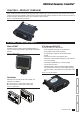
ISOBUS Job Computer : BoomPilot® CHAPTER 1– PRODUCT OVERVIEW BoomPilot (automatic boom section control) is possible in combination with software built into the IC18 Sprayer/NH3 Electronic Control Unit (ECU). The ECU should be combined with the appropriate cable to interface with your BoomPilot system, spray controller and/or spraying machine for quick and easy installation.
ISOBUS Job Computer : BoomPilot® CHAPTER 2 – GETTING STARTED • A firm touch is required when selecting a screen icon. • Settings are NOT automatically saved when selected. The ACCEPT KEY must be selected to save the setting. Select the ESCAPE KEY to escape without saving settings and return to the previous menu. • The menu structure on your display might vary from the one displayed in this User Manual depending on the virtual terminal being used.
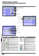
ISOBUS Job Computer : BoomPilot® Operation Mode Information on the Operation screen will vary depending on the parameters set by the user and the OEM. Figure 2-3: Operation Mode Total Area Bounded Alert Warning Speed Remaining Application Time 1.77 B.area Applied Area Home Key 0:00 hh:mm 5.2 0.
ISOBUS Job Computer : BoomPilot® Main Setup Menu Icons and Section Overviews Figure 2-5: Enter Selection Screens Selection Slide Bar with Decrease One Selection and Increase One Selection Arrows Accept Key Escape Key Number Pad Close Number Pad Key Range Maximum Range Minimum Zoom In Key Zoom Out Key Open Number Pad Key Available Selections Up One Selection Accept Key Escape Key Down One Selection OVERVIEW GETTING STARTED SETUP OPERATION Section or Icon Description Section or Icon Description Accept
ISOBUS Job Computer : BoomPilot® CHAPTER 3 – MAIN SETUP Main Setup Mode configures the Setup, OEM, User Interface, Communication and Help options. NOTE: The menu structure on your display might vary from the one displayed in this User Manual depending on the virtual terminal being used.
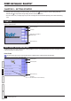
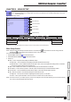
ISOBUS Job Computer : BoomPilot® Master Screen The Master Screen gives access to the systems currently available on your VT. • To view the Master Screen options, select MASTER SCREEN KEY in bottom right corner of any screen. Figure 3-2: Master Screen Master Screen Key on Main Setup Screen Home Screen The Home Screen gives access to the BoomPilot ECU’s available functions: Operation Mode and Main Setup. • To view the Home Screen, select HOME KEY in the top right corner of any screen.
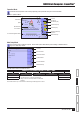
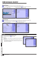
ISOBUS Job Computer : BoomPilot® GPS Setup GPS setup establishes the Overlapping percentage, GPS Alarm and GPS Input. Figure 3-5: GPS Setup Overlapping Overlapping determines the amount of overlap allowed when each boom section is turned on and off using Automatic Boom Section Control. Select from 0%, 50% or 100%. • To select the Overlapping percentage, select an option from the drop down menu or use the UP/DOWN ARROWS to highlight the option.
ISOBUS Job Computer : BoomPilot® OEM The OEM setup menu is password protected and the settings in this menu are directly related to the fitted OEM equipment. To obtain an access code, contact your local dealer or TeeJet Technologies Customer Service. To access the OEM screens: Figure 3-9: OEM 1. From the Main Setup Screen , select OEM. 2. Select OEM. 3. Select the Access Code Entry Box to the right of the menu option. 4. Use the number pad or slide bar to enter the access code. 5.
ISOBUS Job Computer : BoomPilot® USER INTERFACE User Interface allows the operator to select the system virtual terminal (VT) and ECU identification number. 1. From the Main Setup Screen , select USER INTERFACE. Figure 3-12: User Interface Use Preferred VT Use Preferred VT sets the virtual terminal preference to either on or off. If “On” is selected, the preferred VT will be used.
ISOBUS Job Computer : BoomPilot® HELP The Help menu allows the operator to choose between Diagnostics and the display of information about serial number, CAN BUS information, etc. These menus are typically accessed upon Customer Service personnel request only. 1. From the Main Setup Screen , select HELP. 2. Select from: ►Diagnostic – used to provide information regarding the BoomPilot protocol, VT and TECU. ►About – provides information on the console such as software version, build number, etc.
ISOBUS Job Computer : BoomPilot® VT Data The Virtual Terminal (VT) menu provides information regarding the virtual terminal controller (i.e., address version, etc.). • If more terminals/controllers are used, switch between these by pressing the GO TO NEXT VT KEY . • Press the DELETE OBJECT POOL KEY to upload information from the IC18 Job Computer to the Virtual Terminal. NOTE: Restart the IC18 Job Computer to implement and display changes.
ISOBUS Job Computer : BoomPilot® CHAPTER 4 – OPERATION MODE The Operation Screen accesses the working aspects of the BoomPilot ECU including boom section control and trip/application information. NOTE: Settings are automatically saved when selected. NOTE: The menu structure on your display might vary from the one displayed in this User Manual depending on the virtual terminal being used.
ISOBUS Job Computer : BoomPilot® Section or Icon Description Applied Area Displays the actual application per hectare/acre Alarm Displayed if an alarm condition is active GPS Information Displays the current GPS status or mode Boom Sections Displays the active and inactive they are on (spray is blue) or off Sprayer ID Number Displays the soft key number assigned to the displayed IC18 ECU.
ISOBUS Job Computer : BoomPilot® APPLICATION BOUNDARY Application boundaries establish areas where application is and is not applied while using ABSC or BoomPilot. To establish an application boundary: Figure 4-4: Boundary in Progress 1. Drive to a desired location at the perimeter of the field/application area. 2. Press START BOUNDARY KEY . 3. Travel the perimeter of the field/area. 4. Finish boundary: ►Travel to within one swath width of the starting point.
ISOBUS Job Computer : BoomPilot® ALL SECTIONS ON All Sections On will turn all sections on whether you are in an applied area or not. 1. On the Operation Screen KEY . , turn all sections on by pressing the ALL ON NOTE: Pressing and holding the ALL ON KEY will force all sections to remain on. When you release the ALL ON KEY , the sections will go back to the previous mode (auto/manual). Figure 4-7: All On Key 1.77 B.area 0:00 hh:mm 5.2 0.
ISOBUS Job Computer : BoomPilot® APPENDIX A - FACTORY SETTINGS & RANGES SETUP GPS Setup Description Factory Setting Range/Options Overlapping 100% 0%, 50%, 100% GPS Alarm No GPS Data No GPS Data No DGPS Data No GPS Alarms GPS Input Internal Internal RS232 Description Factory Setting Range/Options Delay Off 0.0 0.0 - 10.0 sec Delay On 0.0 0.0 - 10.0 sec Front or Back Mounted Implement Back Front Back Distance from Boom to Mount Point 0.00 0.00 - 50.
B O O M P I LOT® J O B CO M P U T E R U S E R Software Version 0.00 TeeJet Technologies 1801 Business Park Drive Springfield, Illinois 62703 USA Tel: (217) 747-0235 • Fax: (217) 753-8426 www.teejet.