844-R Speed Compensated Application Control User Guide 98-05047 R0
Table Of Contents TABLE OF CONTENTS ............................................................................................................................. 2 INSTALLING THE SPEED SENSOR ASSEMBLY ................................................................................ 4 STEP 1 - LOCATION .................................................................................................................................... 4 Proximity Sensor (optional) ...............................................
Step 4 – Measure................................................................................................................................. 21 Step 5 – Adjustments ........................................................................................................................... 21 DISTANCE COUNTER ................................................................................................................................ 22 SIMULATED GROUND SPEED ...........................................
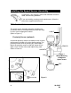
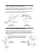
Installing the Speed Sensor Assembly Components: Two magnets, Sensor with attached connector cable, and mounting hardware. If you are installing a radar ground speed sensor, follow the instructions supplied with that unit. STEP 1 - LOCATION The speed sensor assembly should be installed on a non-driven wheel to avoid potential errors that are likely to occur from a slipping drive wheel.
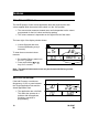
STEP 2 - INSTALLING THE WHEEL MAGNETS Check for pre-drilled holes in the wheel rim. If pre-drilled holes are not available, layout a pattern as shown in figure 3 and drill two 3/8 inch holes, locating them near the outer rim, if possible, and 180° from each other. Place the magnets into each of the two holes on the inside rim and securely fasten using the nuts and washers provided.
Your installation will likely vary from the example. It may be necessary to customize the installation to accommodate your specific machine. Keep in mind that the two magnets must be spaced an equal distance around the wheel. The magnetic sensor must be mounted in-line with the magnets and positioned within 1/8 inch to 3/8 inch from each magnet as they pass the sensor assembly.
Powering Console On/Off POWER ON To power the 844-R on press the P key once. Initially the console displays the software version in the top display. After 5 seconds the display shows the normal operating view. RO SFt 1.04 Ha POWER OFF To manually power the console off, press the and P keys simultaneously. The console saves any new information (area and volume counters) to memory and powers off. RO OFF The console also has an Auto Power Down feature.
Operating Instructions APPLICATOR CHECKOUT Before spraying, check all connections related to the Control System. Be sure connections are made and the sensors and cabling are properly secured. Very Important: Whenever working around chemicals, be sure to wear protective clothing and eyewear. Partially fill the applicator tank with water to purge the system of air and to make a visual check of the liquid outlets to be sure liquid is exiting each outlet as intended.
THE SPRAYING OPERATION The sprayer tank is filled and the solution thoroughly mixed. The application rate and proper nozzles have been determined. The controller has been programmed with the sprayer and application information. Turn the control console on by pressing the P key. RO The Auto/Man key should be switched to “AUTO”. In the Auto mode, when the Delivery switch is “OFF”, the target application rate as well as the target symbol is displayed on the console display.
Features AREA/VOLUME DISPLAY The 844-R Sprayer Control counts application area and measures the total volume applied while the master boom switch is in the “ON” position. The area counter measures treated acres and is dependent on the values programmed for the # of outlets and the tip spacing. The volume measure is dependent on the signal from the flow meter. The lower right of the display window shows: Volume Sprayed and Area Covered (alternating every 3 seconds).
NO FLOW ALARM If the 844-R stops receiving pulses from the flow meter The turbine symbol flashes at the top of the display. This alarm indicates that there is a problem with the flow meter or cabling. PSI 4.8 This alarm occurs only when the Master boom switch is “ON”. 0.0 0 MPH GPA 32.50 Ac FLOW RATE FEATURE The 844-R Sprayer Control measures a flow rate moving through the flow meter in GPM {Imp GPM}.
BOOST MODE The 844-R is capable of boosting the target application rate either up or down in 10% increments. Boost Up To activate the boost up mode: Press the + key. Each subsequent pressing of the + key boosts the target rate up 10%. Up 2.4 20 39.50 GPA Ac The amount boosted up is shown on the display temporarily (approx. 2 seconds). The target symbol flashes anytime that you are in the boost mode to alert the operator of the “off target” condition.
The operator can either use the + key to get back in 10% increments The operator can push the + and keys simultaneously to get back to the target in one step. AUTO POWER DOWN The 844-R console is designed to power itself off after 10 minutes of no inputs. This feature keeps the console from draining the battery on the sprayer if the operator inadvertently leaves the console powered on for an extended period.
Programming Guidelines Make sure that all hardware components are properly installed and tested. Before the programming process starts, confirm that the console and all sensors are working properly. IMPORTANT PRELIMINARY INFORMATION Before starting, we recommend that you review the following Programming Guidelines that control the programming process: To enter the program mode, see the appropriate program section you wish to enter in this manual.
SELECTION OF WORKING UNITS In this step select the units you will be using. The 844-R is capable of working in: GPA (US Gallons Per Acre) IMP (Imperial Gallons Per Acre), US Use the + and keys to select the appropriate units. Press the P key to accept the value and advance to the next program step. RO RESET TO DEFAULTS ***********THIS STEP MAY NOT APPEAR*********** If you did NOT make any changes to the units, this step is skipped and you are automatically advanced to the Speed Sensor Calibration Step.
FLOW METER PULSES In this step the flow meter calibration number can be entered manually from the factory calibrated meter. Your controller is preset to match the flow meter installed on the Redball pump unit. If changes are necessary: Cal 4000 Use the + or keys to modify the value on the display to match the tag on your flow meter. Press the P key to advance to the next step. RO TIP SPACING Enter the spacing between the spray nozzles or micro tubes in Inches 30 keys to adjust Use the + or the value.
SPEED SENSOR CALIBRATION During Speed Calibration, the 844-R automatically senses if a Wheel Speed or Radar Speed Sensor is being used. Proximity/Magnetic Pulses The speed sensor must be calibrated in order to provide the proper speed and area readings. The value for this step is the number of pulses generated by the speed sensor in 300 ft. 250 Automatic Calibration: Mark off a distance of exactly 300 ft. Press and hold the + and keys simultaneously to activate the auto calibration mode.
It is best to repeat the automatic speed calibration process at least twice and use the average of the speed calibration numbers. To manually enter the radar calibration value, first press the Auto/Man key to put the console into radar mode. When the control console is in the radar mode, “RAD” is displayed in the lower left of the console display. Now use the + or keys to adjust the value. Once the correct value is been entered, press the P key to validate this value and advance to the next step.
Flow Meter calibration The flow meter supplied with your system has been calibrated at the factory and under normal circumstances there may be no need to re-calibrate it. However, the factory calibration setup may not reflect specific sprayer plumbing. Before spraying actual chemicals, the flow meter should be checked for proper calibration. To do so, use either of the following methods: METHOD 1 – KNOWN VOLUME Step 1 – Known Value Select a known volume of water (n) to be pumped through the flow meter.
Step 5 – Entering a New Flow Meter Calibration Number The number displayed in the lower left hand corner of the display is the new flow meter calibration number. Record this number, enter the System Setup Mode and advance to the Flow Meter Calibration Number step. Enter the new value from the test into this step and exit the System Setup Mode.
Step 3 – Calculated Flow Multiply the number of tips to be measured by the size (or individual flow rate) of each tip. Example: 10 tips x 0.4 GPM {0.32 Imp GPM} = 4GPM {3.2 Imp GPM} Step 4 – Measure Turn the controller on to activate pump. Toggle on the Master Boom Switch and the number of sections to be measured. Insure that the pressure at the boom is maintained at 40PSI. While spraying, press and hold the key in. Look at the lower right display to see if the measured flow matches the calculated flow.
DISTANCE COUNTER This step is a feature, not a calibration step. No specific value needs to be entered here for the controller to operate correctly. This feature measures distance in feet. It can be used to confirm Automatic Speed Calibration (see note below). To activate the counter, press the + key. To stop the counter, press the + key again. To clear an existing distance, press and the + and keys simultaneously.
How To Use To activate the simulated speed, set a value other than zero in the Simulated Ground Speed step as indicated above. Upon exiting the programming mode, the simulated ground speed is in effect, and appears in the speed area of the display (lower left quadrant). The tractor symbol flashes when a simulated speed is in effect. Once the sprayer begins moving and the 844-R receives actual speed pulses, the simulated speed feature is deactivated.
MINIMUM PRESSURE SETTING Set the minimum pressure that the controller will be allowed to regulate to. Sometimes when the applicator speed slows down, the control system will regulate the pressure so low that it falls below the pressure required to open the check valves on the individual nozzle bodies. This is typically set to the minimum recommended pressure nozzle body check valves. Use the + or keys to adjust the minimum pressure. Press the P key to advance to the next step. RO PSI 10 Min PrS I.e.
FLOW RATE SELECTION Next, the tip icon in the top section of the display starts flashing. This value represents the flow capacity of a single orifice or Micro Tube in Gallons Per Minute (GPM) at 12 PSI. Using flow capacity information from the manufacturers documentation, set this to the correct value. Use the + or keys to change the value. Press the P key to advance to the next step RO PSI 12 6.0 2.0 MPH GPA 0.019 CALCULATION STEPS The following two steps are calculation or informational steps only.
Pressing the P key again will take you back to the pressure calculation step. RO Known Pressure Calculation Adjust the pressure value to the desired operating pressure and the speed value will automatically change to reflect the approximate speed required to achieve the programmed target rate at the pressure selected. This gives an indication of the speed range expected at the desired operating pressure range. Use the + or value.
Troubleshooting Guide CONDITION POSSIBLE CAUSES SOLUTION 1. Application Rate Units (GPA) continually flash on/off. A. Continuous discrepancy of 10% or more between Target Application Rate and Actual Application Rate. PROGRAMMING Check all components and programming steps related to flow. B. Flow meter pulses In the System Setup Mode, move to the Flow Meter Pulses section on page 16. Enter the factory calibrated flow meter pulse rate located on the tag accompanying the flow meter.
Troubleshooting Guide (Cont.) C. Flow meter pulses incorrect D. Speed sensor installed incorrectly In the System Setup Mode, move to the Flow Meter Pulses section on page 16. Enter the factory flow meter pulse rate located on the tag accompanying the flow meter. One or more of the wheel sensor magnets are not consistently sending a pulse to the monitor. The distance between the sensor and the magnets is incorrect. Ground debris can accidentally move the sensor out of position.
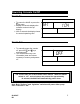
Quick Reference Guide SYSTEM SETUP MODE • The Delivery switch must be off. Press + or keys while simultaneously P P pressing the key. Press the key again to enter the System Setup Mode. RO Step Units RO Display US, INP Description My Values Select US or Imperial gallons for your application units by using + or keys. Proceed to next step with P key. Flow Meter Pulses; Value from flow meter label. Adjust by using + or keys. Proceed to next step with P key.
APPLICATION SETUP MODE The Master boom switch must be off. Press the P key twice to enter the Application Setup Mode. • RO Step Display Target Application Rate Calculation Step Description My Values Target application rate (GPA). Use the + and - keys to adjust the value. Go to next step with P button. keys to Diagnostic tool only. Use the + or adjust the flashing values (pressure or speed). Changes to spraying parameters will be calculated immediately.
NOTES 98-05047 R0 31
Midwest Technologies Illinois, LLC 2864 Old Rochester Road Springfield IL 62703 USA 217-753-8424 98-05047 R0