
Operation Manual


8
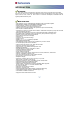
CONTROLS/FUNCTIONS
FRONT/REAR PANEL
Watchin
g
TV status
(
Live mode
)
OSD operatin
g
status
(
OSD mode
)
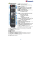
1. Powe
r
Turns the receiver on/off.
2. Menu To enter or exit the Main Menu.
3. Exit To chan
g
e a previous menu or live mode. Current channel displa
y
s in VFD displa
y
screen.
4. Volume +/- To chan
g
e volume level To chan
g
e parameter value.
5. OK To o
p
en channel list To Select / Confirm an item
6. Channel +/- To chan
g
e current channel. To move cursor up/down.
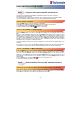
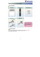
Connector Functions
1. CABLE IN IDC-169-2 FEMALE Cable si
g
nal input to di
g
ital tune
r
2. LOOP OUT IEC-169-2 MALE Loop-throu
g
h output from di
g
ital tune
r
3. LNB INPUT IDC-169-24 FEMALE IF Input from LNB to di
g
ital tune
r
4. LNB OUTPUT IDC-169-24 FEMALE IF loo
p
-throu
g
h out
p
ut from di
g
ital tune
r
5. L
A
N RJ-45 10Base-T
/
100Base-T
x
Ethernet
6. USB USB
A
-t
y
pe USB 2.0
7. e-SAT
A
E-SAT
A
External SAT
A
8. RS232 DB-9 Low speed serial port
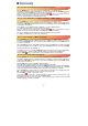
9. HDMI HDMI Di
g
ital Video/Audio Output
10. SPDIF Fiber O
p
tic Di
g
ital audio out
p
ut
(
O
p
tical
)
11. S-
V
IDEO MINI-DIN S-VHS Out
p
ut
12. Component Out RCA cinch Component video output
(
Y, Pb, Pr connectors
)
13. VIDEO RCA cinch Composite video output
14. Audio L/R Out RCA cinch Left/Ri
g
ht audio output
15. TV/VCR SCART SCART CVBS, RGB Video Input/Output, Audio Input/Output
16. RF OUT UHF 21-69 IEC 169-2 MALE Out
p
ut to TV
17. TV ANT IN IEC 169-2 FEMALE In
p
ut from analo
g
terrestrial antenna
18. Power Cord
(
See Pa
g
e 7
)
Receives electric
p
ower.