
Operation Manual

RUNRACE : Service & Maintenance Manual - rev. 2.0
Page 6.40
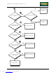
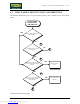
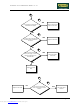
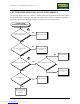
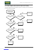
Follow the procedure step by step to correctly diagnose the problem. Take particular care with the
checks highlighted by circled numbers, which are described in detail below:
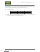
(1) See the following table:
Photocell Photocell board SW
Siemens SFH910 GF92015-B M3S10
Optek OPB610 GF970711 RR52V2
(2) Place the tester probes in series with the motor cable. When the “↑” or “↓” keys are pressed
the measured steady-state current should be less than 6 A.
Downloaded from www.Manualslib.com manuals search engine