
Operation Manual

RUNRACE : Service & Maintenance Manual - rev. 2.0
Page 6.38
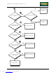
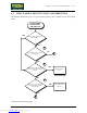
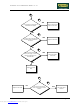
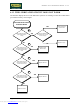
Follow the procedure step by step to correctly diagnose the problem. Take particular care with the
checks highlighted by circled numbers, which are described in detail below:
(1) The machine is considered to have reached a travel limit when the corresponding limit switch
is tripped. The lower limit switch is tripped when its lever is pressed, while the upper limit
switch is tripped when its lever is released.
(2) If the machine fails to move downward, place the tester probes between pins 4 (ground) and 3
(signal) of connector CN2 on the up-down board: the measured voltage should be
approximately 4 Vdc. If the machine fails to move upward, place the tester probes between
pins 4 (ground) and 2 (signal) of connector CN2 on the up-down board: the measured voltage
should be approximately 4 Vdc.
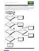
(3) If the machine fails to move downward, place the tester probes between pins 15 (ground) and
14 (signal) of the free connector CN1: the measured voltage should be approximately 4 Vdc.
If the machine fails to move upward, place the tester probes between pins 15 (ground) and 13
(signal) of the free connector CN1: the measured voltage should be approximately 4 Vdc.
(4) If the machine fails to move downward, place the tester probes between pins 15 (ground) and
14 (signal) of connector CN1 on the CPU board: the measured voltage should be
approximately 4 Vdc. If the machine fails to move upward, place the tester probes between
pins 15 (ground) and 13 (signal) of connector CN1 on the CPU board: the measured voltage
should be approximately 4 Vdc.
(5) DL1 corresponds to the upper limit switch, while DL2 on SMD board / DL3 on traditional
board corresponds to the lower limit switch.
(6) Disconnect the 2 connecting cables of the relevant limit switch and place the tester probes
across them: the measured voltage should be approximately 12 Vdc.
(7) To check the upper limit switch, place the tester probes between pins 6 (ground) and 3 (signal)
of connector CN3 on the up-down board: the measured voltage should be 12 Vdc. To check
the lower limit switch, place the tester probes between pins 6 (ground) and 4 (signal) of
connector CN3 on the up-down board: the measured voltage should be 12 Vdc.
Downloaded from www.Manualslib.com manuals search engine