
Operation Manual

RUNRACE : Service & Maintenance Manual - rev. 2.0
Page 6.35
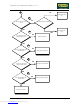
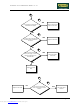
(9) Place the tester probes in series with the motor cable. When the “↑” or “↓” key is pressed the
measured steady-state current should be less than 6 A.
(10) Slightly lift the connector on the photocell and place the tester probes between pins 4 (ground)
and 2 (signal). When the motor moves, the tester should detect the pulses generated by the
photocell.
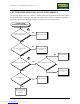
(11) Place the tester probes between pins 4 (ground) and 1 (signal) of connector CN2 on the up-
down. board. When the motor moves, there should be a level changing for each 0.5% change
in the machine elevation.
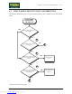
(12) As for step (11), but with the tester probes between pins 15 (ground) and 12 (signal) of the
free connector CN1.
(13) As for step (11), but with the tester probes between pins 15 (ground) and 12 (signal) of
connector CN1 on the CPU board.
Downloaded from www.Manualslib.com manuals search engine