
Operation Manual


RUNRACE : Service & Maintenance Manual - rev. 2.0
Page 6.29
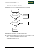
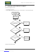
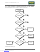
Is the inv erter control PWM signal at
the output of the CPU board correct?
A
YES
Check and/or replace
cables RN-1 and/or RN-2
Replace the CPU board
NO
6
5
YES
Replace the inv erter
interf ace board
NO
Is the inv erter control PWM signal at
the input of the inv erter interf ace
board correct?
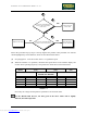
Follow the procedure step by step to correctly diagnose the problem. Take particular care with the
checks highlighted by circled numbers, which are described in detail below:
(1) See paragraph 9.1. to set the inverter and 8.7. to regulate the speed.
(2) When the machine is in operation, check that the speed shown on the machine display and
inverter SJ100 operating frequency correspond to the values shown in the tables below.
SPEED
(Km/h)
PWM SIGNAL
(Vdc)
ANALOG SIGNAL
(Vdc)
FREQUENCY
(Hz)
CPU BOARD INVERTER
INTERFACE BOARD
INVERTER
DISPLAY 10-3/CN1 10-3/CN2 5-6/CN1 L-0 DISPLAY
2.0 4.66 4.66 0.772 0.772 7.9
6.0 3.91 3.91 2.15 2.15 23.9
12.6 2.68 2.68 4.50 4.50 50.0
20.0 1.30 1.30 7.14 7.14 79.6
25.00 0.36 0.36 8.93 8.93 99.5
Table 6.7-1
Obviously, the voltages and frequencies quoted above are nominal values.
For the Hitachi J100 inverter, the data given in the above tables will be slightly
different, but still comparable.
Downloaded from www.Manualslib.com manuals search engine