
Operation Manual


RUNRACE : Service & Maintenance Manual - rev. 2.0
Page 3.13
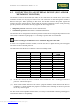
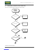
• +12 Vdc signal
This is the DC voltage output by the CPU (pin 10-9 of connector CN2) which enters the pump
interface board (pin 2-1 of connector K1). This voltage reaches one terminal of the relay which
drives the pump.
• Start pump signal
This is the signal output by the CPU (pin 12-9 of connector CN2) to the pump interface board
(pin 4-1 of connector K1) to start the lubrication pump. The signal is normally at logic level low
(0 Vdc), and is asserted (5 Vdc) to start the pump. In practice, this signal pulls down the voltage
on the other terminal of the relay which drives the pump, causing the relay to close the contact,
thereby connecting the 220 VAC supply voltage to the pump.
When the lubrication time has elapsed, the CPU resets the start pump signal, disconnecting the
supply voltage from the pump and thus causing it to stop.
• Oil low signal
This is the signal output by the pump to the pump interface board (pin 4-5 of connector KR6) to
indicate that the oil level in the reservoir is low. The signal is normally at logic level low (0
Vdc), and is asserted (5 Vdc) to indicate the oil low condition. The signal goes out from the
pump interface board (pin 3-1 of connector K1) and enters the CPU board (pin 11-9 of
connector CN2).
WARNING: The pump interface board also functions as a distribution board for the
220 VAC mains voltage. Depending on the machine version, the pump interface
board supplies the voltage to the up-down board, the inverter, the power supply, the
pump and the cooling fans of the motor and motor guard. What’s more, in the
machine version with LENZE inverter, this board also receives the input from the
Pump interface
board
CPU board
12
-
9
Oil Low
Enable
11-9
4
-
1
1-2-3/KR6
3-1
CN2
K1
Pump
4
-
5/KR6
220 VAC
Oil Low
10
-
9
+12 Vdc
2
-
1
Downloaded from www.Manualslib.com manuals search engine