
Operation Manual


RUNRACE : Service & Maintenance Manual - rev. 2.0
Page 3.12
3.4.3. THE SIGNALS
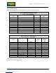
In machines equipped with a pump, cables RN-3 and RN-4 change as follows:
RN-3: Internal connecting cable
CPU – Free connector
CPU board
CN1
Signal Color Free
CN3
1 CTS Blue 1 1
2 DSR Brown 1 2
3 RX Gray 3
4 RTS White 4
5 TX Violet 5
6 GND Red 6
7 BUS A Black 7
8 BUS B Orange 8
9 GND Brown 2 9
10 +12 Vdc 10
11 Oil reservoir level Blue 2 11
12 Start pump command 12
RN-4: Internal connecting cable
Free connector – Serial ports
Free
CN4
Signal Color Serial ports
CN1
Pump inter.
board
K1
1 CTS Blue 1 1 -
2 DSR Brown 1 2 -
3 RX Gray 3 -
4 RTS White 4 -
5 TX Violet 5 -
6 GND Red 6 -
7 BUS A Black 7 -
8 BUS B Orange 8 -
9 GND Brown 2 - 1
10 +12 Vdc - 2
11 Oil reservoir level Blue 2 - 3
12 Start pump command - 4
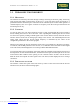
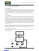
The machine controls the lubrication via the CPU board, the power distribution board and the oil
pump as shown in the figure below:
Downloaded from www.Manualslib.com manuals search engine