
Operation Manual


RUNRACE : Service & Maintenance Manual - rev. 2.0
Page 3.9
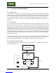
The elevation control utilizes the following signals:
• Up signal
This is the signal generated by the CPU board (pins 13-15 of connector CN1) to enable
movement of the up-down motor in the upward direction. Under normal conditions the signal is
at logic level low (-0.4 Vdc), and it goes high (4.0 Vdc) to actuate the motor. The signal remains
high for the entire duration of the movement.
The signal enters the up-down board (pin 2-4 of connector CN2) and enables movement of the
motor in the desired direction.
• Down signal
This is the signal generated by the CPU board (pin 14-15 of connector CN1) to enable
movement of the up-down motor in the downward direction. Under normal conditions the signal
is at logic level low (-0.8 Vdc), and it goes high (4.0 Vdc) to actuate the motor. The signal
remains high for the entire duration of the movement.
The signal enters the up-down board (pin 3-4 of connector CN2) and enables movement of the
motor in the desired direction.
• Motor voltage signal (Vdc)
This is the dc voltage generated by the up-down board (pins 1-2 of connector CN3) to supply the
up-down motor. Its absolute value is 48 Vdc, and the motor will rotate either clockwise or
anticlockwise depending on its polarity. In consequence, the incline of the machine will increase
or decrease.
• Pulse signal
This is a square wave signal, alternating between logic level low (0 Vdc) and logic level high (5
Vdc), generated by the photocell in response to movements of the up-down motor. Each pulse
corresponds to a slot of the encoder wheel, which is incorporated into and moves with the motor
itself. The signal enters the up-down board (pin 2-4 of connector CN1) and is used by the up-
down board for controlling the movement.
The photocell also outputs a direction signal, which varies from logic level high (5 Vdc) to low
(0 Vdc) depending on whether the motor is moving in a clockwise or anticlockwise direction.
This signal is input to the up-down board (pin 3-4 of connector CN1).
To operate correctly, the photocell requires a 5 Vdc supply voltage which is provided by the up-
down board (pins 1-4 of connector CN1).
• Status signal
This is the square wave signal generated by the up-down board (pin 1-4 of connector CN2) that
changes its logic level (level low 0 Vdc and level high 5 Vdc) whenever the up-down board
receives from the photocell a number of pulses corresponding to an 0.5% variation in the
elevation.
This signal provides the CPU board (pin 12-15 of connector CN1) with an indication of the
change in machine incline. By counting the number of transitions, the CPU determines the
current elevation and, comparing it with the desired value, determines whether to continue
asserting the Up or Down signal to continue the movement, or whether on the other hand the
desired elevation has been reached, and the Up or Down signal can be reset.
Downloaded from www.Manualslib.com manuals search engine