
Operation Manual


RUNRACE : Service & Maintenance Manual - rev. 2.0
Page 2.15
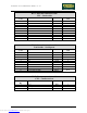
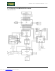
RN-5T: Inverter cable
Inverter interface board – Inverter – Motor thermal cutout
Inverter interf.
board
CN1
Signal Color Inverter Motor thermal
cutout
1 Reference White PV24 -
- Thermal cutout
reference
Red PV24 1
- NC thermal cutout Red 1 2
2 Start Gray FW -
3 NC Alarm Violet AL1 -
4 Alarm reference Red AL0 -
5 Vref (0-10 Vdc) Brown 0 -
6 Vref reference Black L -
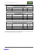
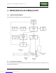
RN-8: Low voltage power supply cable
Power supply – Inverter interface board
Power supply
CN2
Signal Color Inverter interf.
board
CN4
1 + 5 V Yellow 4
2-4-5 Ground Black 3
3 + 12 V Red 2
6 - 12 V Blue 1
Downloaded from www.Manualslib.com manuals search engine