
Operation Manual


RUNRACE : Service & Maintenance Manual - rev. 2.0
Page 9.11
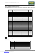
9.6.1. MODIFIED PARAMETER SETTINGS
The following table shows the parameters which must be configured with a different value from the
inverter defaults:
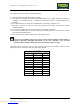
Parameter Description Value
A03 Base frequency 50
A04 Maximum frequency setting 110
A11 External frequency setting start 0.8
A12 External frequency setting end 110
A44 Control method setting 02
A61 Frequency upper limit setting 0
A81 Selection of AVR function 01
A82 Selection of voltage of AVR function for the motor 240
b12 Level of electronic thermal setting 11.00
b13 Selection of electronic thermal characteristic 01
b22 Level of overload restriction setting 16.50
b83 Carrier frequency setting (KHz) 16.0
b90 Dynamic braking usage ratio 10
C03 Function of terminal 3 setting 12
C13 Condition of terminal 3 setting 01
F02 Acceleration 15.0
F03 Deceleration 5.0
H01 Autotuning mode setting 0
H02 Motor data selection 01
H03 Motor capacity setting 2.2
H04 Motor poles setting 4
H05 Motor constant K
p
setting 80
H06 Motor stabilization constant 100
H30 Motor constant R1 (Autotuning data) 1.124
H31 Motor constant R2 (Autotuning data) 0.888
H32 Motor constant L (Autotuning data) 7.79
H33 Motor constant Io (Autotuning data) 5.25
H34 Motor constant J (Autotuning data) 20.0
Before modifying the value of function C0, modify the value of function C13.
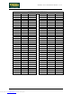
9.6.2. MONITOR FUNCTION PARAMETERS
Parameter Description
d01 Motor output frequency
d02 Motor current draw
d04 Direction of movement
d05 Status monitor of intelligent terminal input signals
d06 Status monitor of intelligent terminal output signals
d07 “Converted” motor output frequency
d08 Monitor of last alarm condition
d09 List of the last error conditions
Downloaded from www.Manualslib.com manuals search engine