
Operation Manual


RUNRACE : Service & Maintenance Manual - rev. 2.0
Page 7.35
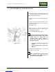
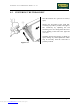
7.27. DISASSEMBLING THE PHOTOCELL
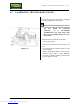
Figure 7.27-1
Carry out the procedures described in paragraphs
7.8. “Disassembling the motor guard” and 7.10.
“Disassembling the front plate”.
1. Disconnect connector a on the PHOTOCELL
board.
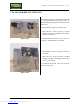
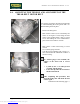
2. Using a 10-mm wrench, back off the 2 cover
fixing screws b on the protective housing of
the encoder wheel.
3. Open the cover c.
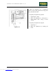
4. Back off the 2 screws d fixing the
PHOTOCELL board to the support, using a
small Philips screwdriver.
5. Remove the PHOTOCELL board.
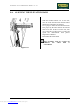
There are 2 different photocell versions,
distinguished by the name of the printed
circuit board on which they are
mounted. Each version requires a
specific microcontroller SW version on
the up-down board:
• circuit board GF920415 requires SW
M3S10;
• circuit board GF970711 requires SW
RR52V2.
To reassemble the PHOTOCELL, carry out the
above steps in reverse order.
After completing the procedure, adjust
the centering of the PHOTOCELL as
described in paragraph 8.8. .
Downloaded from www.Manualslib.com manuals search engine