
Operation Manual

RUNRACE : Service & Maintenance Manual - rev. 2.0
Page 7.33
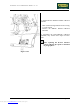
7.25. DISASSEMBLING THE LEAD SCREW NUTS
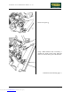
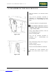
Figure 7.25-1
1. Raise the machine to its maximum incline
position.
2. Carry out the procedures described in
paragraphs 7.8. “Disassembling the motor
guard” and 7.10. “Disassembling the front
plate”.
3. Overturn the machine on its right hand side.
If the automatic lubrication system is
installed, ensure that the oil reservoir
cap is securely closed.
4. Using a large Philips screwdriver, back off
the 9 self-tapping screws a.
5. Remove the belt guard b.
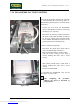
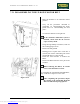
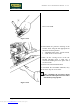
6. Carry out the procedure described in
paragraph 7.24. “Disassembling the
elevation bars”.
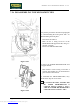
Figure 7.25-2
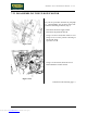
7. Back off the bearing clamp screw c using a 4-
mm hex T wrench.
8. Rotate the bearing clamp d.
9. Remove the LEAD SCREW NUT GROUP.
To reassemble the LEAD SCREW NUT
GROUP, carry out the above steps in reverse
order.
Downloaded from www.Manualslib.com manuals search engine