
User's Manual

3-3
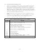
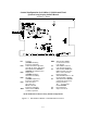
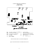
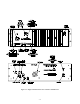
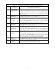
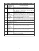
TABLE 3-1 OPERATOR'S SWITCHES, CONTROLS AND INDICATORS
Item
No.
SWITCHES
CONTROLS &
INDICATORS
FUNCTIONAL DESCRIPTION
1 POWER ON/OFF
SWITCH
A toggle switch applies the AC power to the power supply and the
DC voltage to the transceiver. The transceiver is switched to ON in
the toggle UP position the transceiver is switched OFF in the toggle
DOWN position.
2 POWER ON LED
INDICATOR
A GREEN LED Indicates when the POWER ON/OFF switch is set to
ON and voltage is applied to the transceiver.
3 SQUELCH
CONTROL
A linear potentiometer determines the squelch threshold level. When
the SQUELCH CONTROL is rotated in the counter-clockwise
direction, the SQUELCH GREEN LED indicates that the squelch is
connecting demodulated audio to the VOLUME control.
4 SQUELCH
INDICATOR
A GREEN LED indicates the squelch circuit is connecting demodulated
audio signal to the VOLUME control.
5 Tx ON
AMBER LED
INDICATOR
An AMBER LED indicates when the transceiver is keyed by the
microphone PRESS-TO-TALK (PTT) switch or remote land line, and
the transceiver is operated in the Tx mode. The Tx ON AMBER LED
switches OFF, when the transceiver is operated in the receive mode.
6 VOLUME
CONTROL
A logarithmic potentiometer determines the audio level applied to the
internal speaker when the transceiver is operated in the receive
mode. When the SPEAKER/PHONE connector is in use the internal
loudspeaker is disconnected and the VOLUME CONTROL sets the
audio level applied to the external speaker or headphone.
7 MIC/PTT
CONNECTOR
A standard 0.2 inch 3-pole jack is provided to connect a microphone
with PTT to the transceiver front panel.
8 TX LABEL Indicates the frequency programmed for transmit.