
User's Manual
3-1
SECTION 3
OPERATING INSTRUCTIONS
3.1 INTRODUCTION
This section includes a functional description of each switch, control, indicator and connector
located on the front and rear panels of the portable transceiver, including the PRESS-TO-TALK
switch located on the microphone. Operating instructions for transmit/receive and the special
functions are also included.
3.2 INSTALLATION
The TSC-4400 Transceiver is designed to be mounted in a 19 inch rack. An AC Line cord P/N
927002-1 is supplied for connection to AC Power. A 9 Pin connector (mates with Positronic
GM9MSCG000VL or equivalent) and a 25 Pin Connector (mates with Amphenol 17D-B-25S
or equivalent) are provided for connection with external DC and 2 Wire or 4 Wire 600 ohm
dedicated lines. A 50 ohm "N" Type connector is provided for connection to an external
antenna. Refer to Section 2 for frequency selection and remote control setup details.
(1) Mount Transceiver in 19 inch rack with 4 screws.
(2) Install Microphone in Microphone (PTT) connector if required.
(3) Ensure that Transceiver POWER ON/OFF switch is set to OFF.
(4) Install AC line cord in AC chassis connector on rear panel.
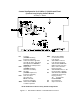
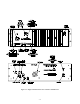
(5) Install Remote Control connector to 9 Pin or 25 Pin connector as required. (Refer to
Figure 3-1 for connector pin outs.)
(6) Connect antenna connector to rear panel chassis N Type connector.
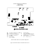
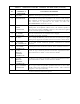
3.3 OPERATOR'S SWITCHES, CONTROLS AND INDICATORS
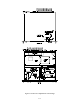
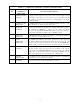
A view of the front and rear panel is given in Figure 3-1. A functional description of each of
the operator's switches, controls and indicators, and the microphone PRESS-TO-TALK switch,
is given in Table 3-1, Operator's Switches, Controls and Indicators.