
User's Manual
2-1
SECTION 2
PREPARATION FOR USE AND STORAGE
2.1 INTRODUCTION
This section provides the information required for custom configuration and storage of the
Single Channel Transceiver. Custom system configuration includes customizing remote control
board functions, and Transmit/Receive frequency selection.
CAUTION: Antenna must be connected to transceiver before transmitting or permanent
damage to the output stage may occur.
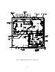
2.2 DISASSEMBLY/ASSEMBLY (Refer to Figure 2-1)
2.2.1 Remove/Replace Top Dust Cover Assembly
REMOVAL
(1) Remove and retain twelve screws securing top dust cover to the 19" rack chassis.
(2) Please note the location of the three longer screws which travel through the heatsink
shims rivetted to the inside of the top cover.
(3) Lift cover clear of chassis to expose internal view of transceiver as shown in Figure
2-1.
REPLACEMENT
(1) Position top cover on chassis.
(2) Position one screw in each corner of the top cover mounting holes. Place the three
longer screws into their correct holes located over the internal transceiver module.
(3) Secure cover to chassis with remaining screws.
2.2.2 Remove/Replace Transceiver Module
REMOVAL
(1) Remove dust cover as described in paragraph 2.2.1.
(2) Disconnect RF and DC connectors from rear of transceiver module.
(3) Remove and retain the screws securing the top cover of the internal transceiver
module.
(4) Remove and retain two screws and two washers securing flat cable to the side of the
transceiver module and disconnect the flat cable. Disconnect the flat cable running out
of the transceiver module at the connector on the external memory set board.
(5) Remove and Retain four countersunk screws securing transceiver module to front
panel.