
User's Manual


TECHNISONIC INDUSTRIES LIMITED
www.til.ca
TFM-550 Installation & Operating Instructions TiL 99RE262 Rev A Issue 8
A-1
APPENDIX – TO “INSTALLATION INSTRUCTIONS”
POST INSTALLATION EMI TEST
PURPOSE
The purpose of this test is to identify any interference that the TFM-550 may cause with existing
aircraft systems. As the TFM-550 installation may include the ATC-550 antenna tuner controller,
this test, as required, will also identify any interference caused by the ATC-550.
TEST CONDITIONS
The TFM-550 transceiver and any accessories (e.g., RC-550, ATC-550) should be installed and
function tested. The antenna VSWR should be checked. A forward/reverse power check with a in-
line wattmeter should show no more than 10% reflected power. For the following tests, insure that
the power switch is in the high position.
METHODOLOGY
Most of the EMI tests can be accomplished on the ground. In some cases flight testing is required
or is easier. If the aircraft is approved for IFR operations, then it is mandatory that interference
between the TFM-550 Airborne FM and the approach aids be checked in flight.
The GPS should be operational and navigating with at least the minimum compliment of
satellites. The VHF comm should be set to the frequencies indicated with the squelch open.
VOR/DME receivers should be set to the frequencies indicated and selected for display. If
possible, set up a DME ramp test set on the frequencies indicated and adjust the output until the
flags are out of view. The transponder and encoder should be monitored with ramp test
equipment. Set the output of the transponder test set to 3db above the output necessary to
achieve 90% reply. If possible set the ADF to a nearby navigation station.
Modulate the TFM-550 transmitter on the indicated frequencies for at least 20 seconds.
Observe the GPS for any degradation in satellite status or availability or flags. Listen for any
noise or detected audio signals on the VHF comm(s). Listen for any noise or detected audio
signals on the VOR/LOC receiver audio; look for any moment of flags or needles on the
VOR/LOC/GS navigation display(s). Observe the transponder for any loss of reply or spurious
reply.
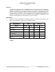
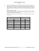
List the power plant, fuel and other electric instruments in the chart provided and note any
anomalies that occur while transmitting. Assess the results.
If the aircraft is equipped with an autopilot or a stability augmentation system, then test fly the
aircraft and verify that operation of the TFM-550 transceiver does not have adverse effects on
these systems. After checking for gross effects at a safe altitude, fly an approach with each of the
different navigation systems coupled to the autopilot (ILS, GPS etc.) and look for any anomalies.
When the installation includes the ATC-550 antenna tuner controller, this test (where indicated by
an asterisk “*”) will also identify any interference caused by the ATC-550. In these cases, the
ATC-550 must be turned on and off by means of its breaker as often as required, while
monitoring the victim equipment.