
User's Manual

TECHNISONIC INDUSTRIES LIMITED
www.til.ca
TFM-550 Installation & Operating Instructions TiL 99RE262 Rev A Issue 8
3-10
3.12 TRANSMITTER DEVIATION ADJUSTMENT
VHF:
1. Remove the bottom cover of the transceiver.
2. Set the VHF operating frequency to 157.000 MHz and connect an appropriate test
receiver to the RF output connector. Ensure that the output of the transceiver is
terminated into a proper dummy load.
3. Key the transmitter and input a +10 dBm (2.5 VRMS), 2.5 kHz audio signal into
microphone input 1.
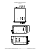
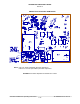
4. Adjust the wideband deviation limit potentiometer, R30 on the VHF Rx/Tx module (see
Figure 3-5) to produce a ±4.20 kHz deviation. Select narrow band mode on the VHF band
and adjust the narrowband deviation limit potentiometer, R76 on the VHF Rx/Tx module
to produce a ±2.10 kHz deviation.
5. Verify that the deviation does not exceed ±5 kHz for wideband and ±2.5 kHz for
narrowband on 138.000 MHz, and 174.000 MHz. Re-adjust R30 or R76 as required, if the
deviation exceeds ±5 kHz or ±2.5 kHz, respectively.
6. Replace the bottom cover.
UHF:
1. Remove the left side cover of the transceiver.
2. Select the UHF band.
3. Set the UHF operating frequency to 457.000 MHz and connect an appropriate test
receiver to the RF output connector. Ensure that the output of the transceiver is
terminated into a proper dummy load.
4. Key the transmitter and input a +10 dBm (2.5 VRMS), 2.5 kHz audio signal into
microphone input 1 if in single mode or microphone input 2 if in dual mode.
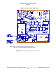
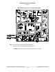
5. Adjust the wideband deviation limit potentiometer, R30 on the UHF Rx/Tx module (see
Figure 3-6) to produce a ±4.20 kHz deviation. Select narrow band mode on the UHF
band and adjust the narrowband deviation limit potentiometer, R76 on the UHF Rx/Tx
module to produce a ±2.10 kHz deviation.
6. Verify that the deviation does not exceed ±5 kHz for wideband and ±2.5 kHz for
narrowband on 403.000 MHz, and 512.000 MHz. Re-adjust R30 or R76 as required, if the
deviation exceeds ±5 kHz or ±2.5 kHz, respectively.
7. Replace the bottom cover.
VHF LOW:
1. Remove the top cover of the transceiver.
2. Set the VLO operating frequency to 41.000 MHz and connect an appropriate test receiver
to the RF output connector. Ensure that the output of the transceiver is terminated into a
proper dummy load.
3. Key the transmitter and input a +10 dBm (2.5 VRMS), 2.5 kHz audio signal into
microphone input 1.
4. Adjust the wideband deviation limit potentiometer, R21 on the VLO Rx/Tx module (see
Figure 3-7) to produce a ±4.20 kHz deviation. Select narrow band mode on the VHF band
and adjust the narrowband deviation limit potentiometer, R16 on the VHF Rx/Tx module
to produce a ±2.10 kHz deviation.
5. Verify that the deviation does not exceed ±5 kHz for wideband and ±2.5 kHz for
narrowband on 30.000 MHz, and 50.000 MHz. Re-adjust R21 or R16 as required, if the
deviation exceeds ±5 kHz or ±2.5 kHz, respectively.
6. Replace the top cover.