
User's Manual

TECHNISONIC INDUSTRIES LIMITED
www.til.ca
TFM-550 Installation & Operating Instructions TiL 99RE262 Rev A Issue 8
3-7
3.7.9 Data Input
Data communications equipment requiring direct access to the modulator and discriminator can
be connected via pins 2 and 11. Data cannot be transmitted in CANADA unless equipment is
approved for use with the TFM-550 by the communications regulatory authority.
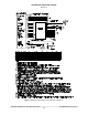
3.8 INTERNAL PROGRAMMING AND GUARD ENABLE/DISABLE JUMPER
The programming and direct frequency entry modes can be disabled by removing the internal
enable/disable jumper strap from pins 1 and 2 of J10. Removal of this jumper will prevent
operation on any frequencies other than those programmed in the 600 memory positions. The
transceiver is always shipped with the two jumpers in the entry enable positions. To place either
of the jumpers in the disable position:
1. Remove the left side of the radio.
2. Set or remove jumpers as necessary.
3. Re-install the left side cover.
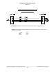
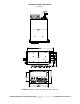
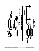
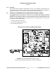
Microprocessor Control Unit (MCU) PCB Module
FIGURE 3-3 Internal Enable/Disable Jumper Locations
(The Guard Entry Disable Jumper has no effect to the TFM-550)