
User's Manual

TECHNISONIC INDUSTRIES LIMITED
www.til.ca
TFM-550 Installation & Operating Instructions TiL 99RE262 Rev A Issue 8
3-6
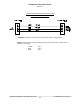
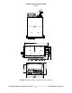
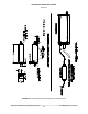
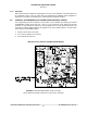
3.7 WIRING INSTRUCTIONS
Figure 3-2 shows all required connections and recommended wire sizes for the TFM-550
Transceiver. If problems with the correct operation of the UHF/FM Transmit function of a TFM-
550 are encountered on a specific airframe, a DC power line filter may be required. Typical
problems encountered are that UHF/FM will not transmit on high power or will not open a
repeater when using a CTCSS transmit tone. Investigation has determined that once the ripple on
the airframes DC (28V) power line becomes excessive, the UHF transmit function and tones will
distort. If the airframes generators are turned off and the UHF/FM transmit function works
correctly from 28 Vdc battery power, the ripple on the DC power line is excessive. The use of DC
power line filter PLF250, p/n 021214-1 is recommended and is available from Technisonic.
3.7.1 Main Power +28 VDC
The main power +28VDC (±15%) is connected to pins 7 and 14 of the transceiver. Both pins
should be connected.
3.7.2 Main Ground
Ground connections for the transceiver are made on pins 8 and 15. Both pins should be
connected.
3.7.3 PTT (Ground Keying)
The PTT line is connected to pin 13 and should be floating when the transceiver is in receive
mode, and grounded during transmit mode. The PTT2 input is on pin 2 of the 9 pin connecter.
3.7.4 Front Panel Back Lighting
Front panel back lighting connection should be made on pin 3 of the transceiver. The opposite
end of this lead should be connected to the panel lighting system of the aircraft. Before
connecting, verify the required panel lighting voltage (28VDC or 5VAC) on the transceiver
configuration control label.
3.7.5 Audio Outputs (600 ohms and 4 0hms)
There are two audio outputs available, (1 & 2). 600 ohm audio output 1 has audio from both VHF
bands and the UHF band in single operator mode. When in dual operator mode, 600 ohm output
1 has audio from the VHF High and Low bands only, while the UHF audio will be on the 600 ohm
output 2. None of these outputs need to be terminated if left unused.
3.7.6 Audio Output Ground
Pin 10 is the ground for both the 4 ohm and 600 ohm audio output signals.
3.7.7 Mic Signal Input
The microphone input signal is to be provided on pin 6, utilizing shielded wire with the shield
grounded to pin 10. Microphone signal 2 is on pin 6 of the 9-pin D connector.
3.7.8 Memory Up/Memory Down
Remote scrolling through the 200 memory positions can be achieved by providing a ground to
pins 4 (up) and 5 (down) through a momentary contact cyclic switch. The memories will scroll
only on the band selected.