
User's Manual

TECHNISONIC INDUSTRIES LIMITED
www.til.ca
TFM-550 Installation & Operating Instructions TiL 99RE262 Rev A Issue 8
3-4
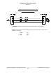
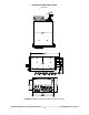
3.6 INSTALLATION - PIN LOCATIONS AND CONNECTIONS (continued)
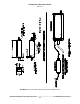
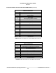
TFM-550 Transceiver
15 Pin D Connections
Pin # Description
1 600
Output 1
2 Data Output
3 Panel Lighting (28VDC or 5VAC)
4 Memory Up
5 Memory Down
6 Mic Signal Input 1
7 Main Power +28VDC
8 Main Ground
9 4 ohm Speaker Output
10 4 ohm/600 ohm Output Ground
11 Data Input
12 DF Audio
13 PTT 1 (Ground Keying)
14 Main Power +28VDC
15 Main Ground
TABLE 3-1 Wire connections on a 15 Pin FEMALE D Connector
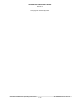
TFM-550 Transceiver
9 Pin D Connections
1 600
Output 2 (UHF Band in Dual Mode)
2 PTT 2 (Ground Keying)
3 Reset
4 Background Debug Signal
5 Ground
6 Programming Voltage In
7 Serial Data Out
8 Serial Data In
9 Mic Signal Input 2
TABLE 3-2 Wire connections on a 9 Pin MALE D Connector