
User's Manual

TECHNISONIC INDUSTRIES LIMITED
www.til.ca
TFM-550 Installation & Operating Instructions TiL 99RE262 Rev A Issue 8
3-1
SECTION 3 – INSTALLATION INSTRUCTIONS
3.1 GENERAL
This section contains information and instructions for the correct installation of the TFM-550,
VHF/FM Transceiver.
Make certain that the correct frequencies are pre-programmed in accordance with the equipment
user's valid FCC operator's license, prior to installation.
3.2 EQUIPMENT PACKING LOG
Unpack the equipment and check for any damage that may have occurred during transit. Save
the original shipping container for returns due to damage or warranty claims. Check that each
item on the packing slip has been shipped in the container. Verify that the equipment display and
backlighting configuration are the same as those ordered.
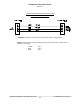
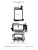
3.3 TRANSCEIVER INSTALLATION
The TFM-550 Transceiver is designed to be Dzus mounted and should be installed in conjunction
with an IN-550 installation kit. See Figure 3-1a for an outline drawing of the unit with dimensions
to facilitate the installation.
3.4 INSTALLATION KIT - CONTENTS
The IN-550 installation kit consists of:
1. One 15 pin Cannon D mating connector (female) complete with crimp pins and hood.
2. One 9 pin Cannon D mating connector (male) complete with crimp pins and hood.
3. Three BNC antenna mating RF connectors (male).
3.5 ANTENNA INSTALLATION
Antenna, Comant P/N CI-292-3 or suitable equivalent, may be utilized for VHF. Antenna, Comant
P/N CI-275 or suitable equivalent, may be utilized for UHF and the Foxtronics model FLX-3050B
antenna/tuning system or Sensor Systems P/N S65-8282-34 may be utilized for the VLO band. A
suitable whip antenna cut for a specific VLO frequency may also be used. The antenna gain of
any above antennas for any band may not exceed a maximum gain of 3 dBi. The antennas shall
be mounted on the bottom of the aircraft whenever possible and must
not be co-located (kept at a
separation distance of more than 20cm from each other when installed). Also they must be installed in
such a way that they always maintain a separation distance of more than 90cm
(36 inches) from any
occupant in the airframe
during operation. Consult with instructions provided with the antennas.
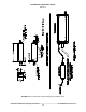
Connect RF cables from antennas to the back of the TFM-550 unit by utilizing the BNC mating
connector provided in the installation kit. The VHF Low band (top) and UHF (middle) BNC
connectors are located on the rear, above the 15 pin D connector and the VHF high band BNC
connector is below the 9 pin D. If an external antenna tuner (ATU) is to be used, the ATC-550
(P/N 991102-1) will have to be utilized to control it. The ATC-550 is an external box to the TFM-
550. See Figure 3-1b.
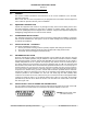
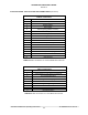
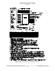
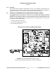
3.6 INSTALLATION - PIN LOCATIONS AND CONNECTIONS
The pin numbers and locations for the 15 pin and 9 pin Cannon D located on the rear of the TFM-
550 transceiver are shown below. Pin connections are listed in TABLES 3-1 and 3-2.
FIGURE 3 15 pin female and 9
pin male connector