
User's Manual
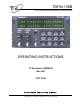

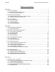
Table Of Contents
- OPERATING INSTRUCTIONS
- 1.1 Controls and Display
- 1.2 Transceiver Basic Operation
- 1.3 About Commands
- SECTION 2
- 2.1 Channel Operating Parameters
- 2.2 Editing Channel Operating Parameters
- 2.3 Scan and Multi-Mode Operation
- 2.4 Controlling User Access
- 2.5 Encrypted Operation
- 3.1 Operator Level 1 Commands
- 3.1.1 Select the Operating Memory for the Main Channel
- 3.1.2 Increase Display Brightness
- 3.1.3 Edit Channel Operating Mode
- 3.1.4 Scroll Backwards through Available Memories
- 3.1.5 Start/Stop Scan
- 3.1.6 Scroll Forewards through Available Memories
- 3.1.7 Edit Channel Operating Frequency
- 3.1.8 Decrease Display Brightness
- 3.1.9 Edit Channel Squelch Mode
- 3.1.10 Command Level Up
- 3.1.11 Toggle memory: current/home
- 3.1.12 Toggle Talk Around
- 3.1.13 Erase Encryption Keys
- 3.2 Operator Level 2 Commands
- 3.2.1 Create/Edit All Channel Information
- L2-1.1. Entering a Memory Number (refer to L1-1 for details)
- L2-1.2. Enter a Scan List & Enabling/Disabling Scan (refer to L2-5 for details)
- L2-1.3. Enter a Text Description (refer to L2-6 for details)
- L2-1.4. Enter an Operating Mode (refer to L1-3 for details)
- L2-1.5. Enter a Frequency (refer to L1-7 for details)
- L2-1.6. Enter the Squelch Parameters (refer to L1-9 for details)
- 3.2.2 Copy Guard to Main
- 3.2.3 Lock Keypad
- 3.2.4 L2-4 not used.
- 3.2.5 Edit Scan List & Enable/Disable Scan
- 3.2.6 Edit Memory Text Description
- 3.2.7 Create Shadow Memory
- 3.2.8 Copy Main to Guard
- 3.2.9 Encryption ON/OFF
- 3.2.10 Command Level Up
- 3.2.11 Command Level Down
- 3.2.12 L2–#. Not Used.
- 3.2.1 Create/Edit All Channel Information
- 3.3 Operator Level 3 Commands
- 3.3.1 Select Boot Channel
- 3.3.2 Assign Key by KeyTag
- 3.3.3 Set Numeric Edit Mode: Decimal or Hexadecimal
- 3.3.4 Display Firmware Release and Version Information
- 3.3.5 Edit Scan Parameters
- 3.3.6 Configure PTT Timer
- 3.3.7 Side Tone Audio Level Adjust
- 3.3.8 PC Data Upload/Download
- 3.3.9 Display Channel Squelch Parameters
- 3.3.10 Command Level Up
- 3.3.11 Command Level Down
- 3.3.12 Unused
- 3.4 Maintenance Commands (Level 4)
- 3.4.1 Set Default Record
- 3.4.2 Set Restricted Level Access Mode
- 3.4.3 Set Command Permissions
- 3.4.4 Set Memory Edit
- 3.4.5 L4-5. not used
- 3.4.6 L4-6. not used
- 3.4.7 Set Frequency Display
- 3.4.8 Assign KeyTags to Encryption Keys
- 3.4.9 Set Squelch Restrictions
- 3.4.10 Command Level Up
- 3.4.11 Command Level Down
- 3.4.12 L4-# not used
- 3.5 Supervisor Commands (Level 5)
- 4.1 Appendix A. Installing the Jumper for Restricted Level Access.
- 4.2 Appendix B. CTCSS Tone and DCS Code Tables
- 4.3 Appendix C. Programming Channel data using TDP and a PC.
- 4.4 Appendix C. 2.5 kHz & 6.25 kHz Valid Frequencies
- 4.5 Appendix D. Default Tables
08RE399 TDFM-136B Operating Instructions
Figure 3-11. Editing the P25 NAC Value.........................................................................................33
Figure 3-12. Editing the P25 ID Call Value......................................................................................33
Figure 3-13. The Screen to Enter a Scan List or Enable/Disable Scan...........................................37
Figure 3-14. The Screen Showing Scan Enabled for this Memory..................................................37
Figure 3-15. Editing the Text Description........................................................................................37
Figure 3-16. Entering a Primary Memory for the Shadow Channel.................................................38
Figure 3-17. Entering a Shadow Channel Memory Number...........................................................38
Figure 3-18. Edit the Shadow Memory Parameter - Text................................................................39
Figure 3-19. The Encryption Enabled for Main...............................................................................39
Figure 3-20. Selecting Main Channel Boot Memory.......................................................................40
Figure 3-21. Selecting the Memory to Assign the Key to................................................................41
Figure 3-22. Selecting the KeyTag to Assign to the Memory...........................................................41
Figure 3-23. Selecting the decrypt option: Any Key or Assigned Key..............................................41
Figure 3-24. Screen to Assign another key or exit..........................................................................42
Figure 3-25. Selecting Edit mode...................................................................................................42
Figure 3-26. Showing the Code Release Information.....................................................................42
Figure 2-27. Select the Scan Revert Mode.....................................................................................43
Figure 2-28. Set the Scan Reply Timer Value.................................................................................43
Figure 3-29. Set the Scan Monitor Timer Value..............................................................................44
Figure 3-30. Set the Scan Delay Timer Value.................................................................................44
Figure 3-31. Set the PTT Timer Value.............................................................................................44
Figure 3-32. Set the Side tone Audio Level....................................................................................45
Figure 3-33. Upload/Download Memory Data to/from the PC.........................................................45
Figure 3-34. Display of the Receive Squelch Parameter Values.....................................................46
Figure 3-35. Display of the Transmit Squelch Parameter Values....................................................46
Figure 3-36. Select the Access Mode from a list.............................................................................48
Figure 3-37. Edit the Level 1 Permissions......................................................................................48
Figure 2-38. Edit the Level 2 Permissions......................................................................................48
Figure 3-39. Edit the Level 3 Permissions......................................................................................48
Figure 3-40. Enable/Disable edit of a specific Memory...................................................................49
Figure 3-41. The Frequency Display Enable/Disable screen..........................................................51
Figure 3-42. A memory with frequency display disabled.................................................................50
Figure 3-43. Step through available keys by SLN...........................................................................51
Figure 3-44. The screen to edit the KeyTag....................................................................................51
Figure 3-45. The screen to assign another KeyTag or exit..............................................................51
Figure 3-46. The Screen to Set Available Squelch Modes for Analog Receive...............................52
Figure 3-47. The Screen to Restrict Editing of the Noise Squelch Value........................................53
Figure 3-48. The Screen to Restrict Available CTCSS Tones.........................................................53
Figure 3-49. Restrict Available DCS Codes....................................................................................53
Figure 3-50. Erase and Re-Program to Factory Defaults................................................................54
Figure 3-51. Transparent Mode......................................................................................................55
Figure 3-52. Edit Maintenance Password.......................................................................................55
Figure 3-53. Edit Supervisor Password..........................................................................................56
Figure 3-54. The Bootloader Screen...............................................................................................56
Figure 3-55. Set Unit ID Number (screen for Main shown).............................................................56
Figure 4-1. The Screw Positions to remove the Left Hand Side Panel............................................59
Figure 4-2. The Shunt Position to Enable Restricted Level Access................................................59
Figure 4-3. The Communicate with PC Command Screen.............................................................61
Figure 4-4. The TDP-136 Radio Programming Software Window...................................................61
ix