
User's Manual
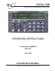

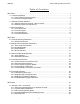
Table Of Contents
- OPERATING INSTRUCTIONS
- 1.1 Controls and Display
- 1.2 Transceiver Basic Operation
- 1.3 About Commands
- SECTION 2
- 2.1 Channel Operating Parameters
- 2.2 Editing Channel Operating Parameters
- 2.3 Scan and Multi-Mode Operation
- 2.4 Controlling User Access
- 2.5 Encrypted Operation
- 3.1 Operator Level 1 Commands
- 3.1.1 Select the Operating Memory for the Main Channel
- 3.1.2 Increase Display Brightness
- 3.1.3 Edit Channel Operating Mode
- 3.1.4 Scroll Backwards through Available Memories
- 3.1.5 Start/Stop Scan
- 3.1.6 Scroll Forewards through Available Memories
- 3.1.7 Edit Channel Operating Frequency
- 3.1.8 Decrease Display Brightness
- 3.1.9 Edit Channel Squelch Mode
- 3.1.10 Command Level Up
- 3.1.11 Toggle memory: current/home
- 3.1.12 Toggle Talk Around
- 3.1.13 Erase Encryption Keys
- 3.2 Operator Level 2 Commands
- 3.2.1 Create/Edit All Channel Information
- L2-1.1. Entering a Memory Number (refer to L1-1 for details)
- L2-1.2. Enter a Scan List & Enabling/Disabling Scan (refer to L2-5 for details)
- L2-1.3. Enter a Text Description (refer to L2-6 for details)
- L2-1.4. Enter an Operating Mode (refer to L1-3 for details)
- L2-1.5. Enter a Frequency (refer to L1-7 for details)
- L2-1.6. Enter the Squelch Parameters (refer to L1-9 for details)
- 3.2.2 Copy Guard to Main
- 3.2.3 Lock Keypad
- 3.2.4 L2-4 not used.
- 3.2.5 Edit Scan List & Enable/Disable Scan
- 3.2.6 Edit Memory Text Description
- 3.2.7 Create Shadow Memory
- 3.2.8 Copy Main to Guard
- 3.2.9 Encryption ON/OFF
- 3.2.10 Command Level Up
- 3.2.11 Command Level Down
- 3.2.12 L2–#. Not Used.
- 3.2.1 Create/Edit All Channel Information
- 3.3 Operator Level 3 Commands
- 3.3.1 Select Boot Channel
- 3.3.2 Assign Key by KeyTag
- 3.3.3 Set Numeric Edit Mode: Decimal or Hexadecimal
- 3.3.4 Display Firmware Release and Version Information
- 3.3.5 Edit Scan Parameters
- 3.3.6 Configure PTT Timer
- 3.3.7 Side Tone Audio Level Adjust
- 3.3.8 PC Data Upload/Download
- 3.3.9 Display Channel Squelch Parameters
- 3.3.10 Command Level Up
- 3.3.11 Command Level Down
- 3.3.12 Unused
- 3.4 Maintenance Commands (Level 4)
- 3.4.1 Set Default Record
- 3.4.2 Set Restricted Level Access Mode
- 3.4.3 Set Command Permissions
- 3.4.4 Set Memory Edit
- 3.4.5 L4-5. not used
- 3.4.6 L4-6. not used
- 3.4.7 Set Frequency Display
- 3.4.8 Assign KeyTags to Encryption Keys
- 3.4.9 Set Squelch Restrictions
- 3.4.10 Command Level Up
- 3.4.11 Command Level Down
- 3.4.12 L4-# not used
- 3.5 Supervisor Commands (Level 5)
- 4.1 Appendix A. Installing the Jumper for Restricted Level Access.
- 4.2 Appendix B. CTCSS Tone and DCS Code Tables
- 4.3 Appendix C. Programming Channel data using TDP and a PC.
- 4.4 Appendix C. 2.5 kHz & 6.25 kHz Valid Frequencies
- 4.5 Appendix D. Default Tables

TDFM-136B Operating Instructions 08RE399
Ta ble of Figures
Figure 1-1. The TDFM-136 front panel showing control & display features..................................... 1
Figure 1-2. The TDFM-136 display – unique parameters highlighted...............................................2
Figure 1-3. The TDFM-136 display - common channel parameters highlighted................................2
Figure 1-4. The active channel display and control points................................................................3
Figure 1-5. Control points for selecting an active memory for the MAIN channel..............................4
Figure 1-6. The Screen showing 'Level 3” in the Command Level Display Position..........................5
Figure 2-1. The user screen to edit the Main frequency....................................................................8
Figure 2-2. The user screen to edit the Guard frequency.................................................................8
Figure 2-3. The user screen to edit the Main frequency for receive..................................................9
Figure 2-4. The user screen to edit the Main frequency for transmit.................................................9
Figure 2-5. The user screen to edit the Main Operating Mode........................................................10
Figure 2-6. The screen to edit the Main Squelch Mode for receive.................................................12
Figure 2-7. The noise squelch edit screen......................................................................................13
Figure 2-8. The screen to edit the Main Squelch Mode for transmit................................................13
Figure 2-9. The CTCSS Tone squelch edit screen..........................................................................13
Figure 2-10. The DCS Code squelch edit screen...........................................................................14
Figure 2-11. The digital NAC squelch edit screen...........................................................................14
Figure 2-12. The digital TalkGroup squelch edit screen..................................................................15
Figure 2-13. The digital ID Call squelch edit screen........................................................................15
Figure 2-14. The Set Unit ID edit screen.........................................................................................16
Figure 2-15. Identifying Graphic for Primary Channel with Shadows..............................................18
Figure 2-16. Identifying Graphic for Shadow Channel....................................................................18
Figure 2-17. The screen to enter a password for restricted level access........................................19
Figure 2-18. The screen to set the Maintenance password............................................................19
Figure 2-19. The Screen to Edit the Level 1 Permissions...............................................................20
Figure 2-20. The Screen showing Mode Select restrictions for Analog Receive.............................21
Figure 2-21. The screen for Enabling/Disabling edit of a specific Memory......................................21
Figure 2-22. The error screen on trying to edit a disabled memory.l...............................................22
Figure 2-23. The screen for Enabling/Disabling Frequency Display for a specific Memory.............22
Figure 2-24. The screen showing memory with frequency display disabled...................................22
Figure 2-25. The screen to select the SLN to assign the KeyTag to...............................................23
Figure 2-26. The screen to edit the KeyTag....................................................................................24
Figure 2-27. The screen to assign another KeyTag or exit..............................................................24
Figure 2-28. Select the Main memory to assign the key to.............................................................25
Figure 2-29. Select the KeyTag to assign to the memory................................................................25
Figure 2-30. Select decrypt on Any Key or Assigned Key...............................................................25
Figure 2-31. The screen to assign another key or exit....................................................................26
Figure 2-32. The analog memory encryption error screen..............................................................26
Figure 2-33. The error screen for no encryption key assigned........................................................26
Figure 2-34. The Encryption Enabled for Main memory screen......................................................26
Figure 3-1. The User Screen to Enter a Memory Number...............................................................28
Figure 3-2. The User Screen to Edit the Operating Mode...............................................................28
Figure 3-3. Trying to start scan on a Channel with Scan disabled..................................................29
Figure 3-4. Start scan on a Channel with Scan enabled.................................................................29
Figure 3-5. The User Screen to Edit the Main frequency................................................................30
Figure 3-6. Editing the Squelch Mode.............................................................................................31
Figure 3-7. Editing the Noise Squelch Value...................................................................................31
Figure 3-8. Selecting the CTCSS Tone Value.................................................................................32
Figure 3-9. Selecting the DCS Code Value.....................................................................................32
Figure 3-10. Editing the P25 TalkGroup Value................................................................................32
viii