
User's Manual
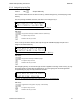
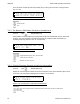
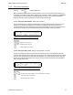
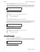
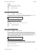
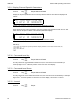
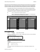
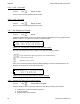
Table Of Contents
- OPERATING INSTRUCTIONS
- 1.1 Controls and Display
- 1.2 Transceiver Basic Operation
- 1.3 About Commands
- SECTION 2
- 2.1 Channel Operating Parameters
- 2.2 Editing Channel Operating Parameters
- 2.3 Scan and Multi-Mode Operation
- 2.4 Controlling User Access
- 2.5 Encrypted Operation
- 3.1 Operator Level 1 Commands
- 3.1.1 Select the Operating Memory for the Main Channel
- 3.1.2 Increase Display Brightness
- 3.1.3 Edit Channel Operating Mode
- 3.1.4 Scroll Backwards through Available Memories
- 3.1.5 Start/Stop Scan
- 3.1.6 Scroll Forewards through Available Memories
- 3.1.7 Edit Channel Operating Frequency
- 3.1.8 Decrease Display Brightness
- 3.1.9 Edit Channel Squelch Mode
- 3.1.10 Command Level Up
- 3.1.11 Toggle memory: current/home
- 3.1.12 Toggle Talk Around
- 3.1.13 Erase Encryption Keys
- 3.2 Operator Level 2 Commands
- 3.2.1 Create/Edit All Channel Information
- L2-1.1. Entering a Memory Number (refer to L1-1 for details)
- L2-1.2. Enter a Scan List & Enabling/Disabling Scan (refer to L2-5 for details)
- L2-1.3. Enter a Text Description (refer to L2-6 for details)
- L2-1.4. Enter an Operating Mode (refer to L1-3 for details)
- L2-1.5. Enter a Frequency (refer to L1-7 for details)
- L2-1.6. Enter the Squelch Parameters (refer to L1-9 for details)
- 3.2.2 Copy Guard to Main
- 3.2.3 Lock Keypad
- 3.2.4 L2-4 not used.
- 3.2.5 Edit Scan List & Enable/Disable Scan
- 3.2.6 Edit Memory Text Description
- 3.2.7 Create Shadow Memory
- 3.2.8 Copy Main to Guard
- 3.2.9 Encryption ON/OFF
- 3.2.10 Command Level Up
- 3.2.11 Command Level Down
- 3.2.12 L2–#. Not Used.
- 3.2.1 Create/Edit All Channel Information
- 3.3 Operator Level 3 Commands
- 3.3.1 Select Boot Channel
- 3.3.2 Assign Key by KeyTag
- 3.3.3 Set Numeric Edit Mode: Decimal or Hexadecimal
- 3.3.4 Display Firmware Release and Version Information
- 3.3.5 Edit Scan Parameters
- 3.3.6 Configure PTT Timer
- 3.3.7 Side Tone Audio Level Adjust
- 3.3.8 PC Data Upload/Download
- 3.3.9 Display Channel Squelch Parameters
- 3.3.10 Command Level Up
- 3.3.11 Command Level Down
- 3.3.12 Unused
- 3.4 Maintenance Commands (Level 4)
- 3.4.1 Set Default Record
- 3.4.2 Set Restricted Level Access Mode
- 3.4.3 Set Command Permissions
- 3.4.4 Set Memory Edit
- 3.4.5 L4-5. not used
- 3.4.6 L4-6. not used
- 3.4.7 Set Frequency Display
- 3.4.8 Assign KeyTags to Encryption Keys
- 3.4.9 Set Squelch Restrictions
- 3.4.10 Command Level Up
- 3.4.11 Command Level Down
- 3.4.12 L4-# not used
- 3.5 Supervisor Commands (Level 5)
- 4.1 Appendix A. Installing the Jumper for Restricted Level Access.
- 4.2 Appendix B. CTCSS Tone and DCS Code Tables
- 4.3 Appendix C. Programming Channel data using TDP and a PC.
- 4.4 Appendix C. 2.5 kHz & 6.25 kHz Valid Frequencies
- 4.5 Appendix D. Default Tables

08RE399 TDFM-136B Operating Instructions
3.3.9 Display Channel Squelch Parameters
Level 3 Key Scope: Main and Guard
Display the Squelch parameters for the currently selected channel. The data are displayed as
follows:
Figure 3-34. Display of the Receive Squelch Parameter Values
When displaying the receive parameters, the noise squelch level appears beneath the “Rx” that
starts the line, this space is blank in the transmit parameters display:
Figure 3-35. Display of the Transmit Squelch Parameter Values
Edit Keys
toggle the squelch parameter display between receive (Rx) and transmit (Tx)
exit
3.3.10 Command Level Up
Level 3 Key Scope: Main and Guard
This key selects the next HIGHER Command Level, the Command Level is indicated by a
subscript digit in the 4
th
character position on the lower row of the display.
3.3.11 Command Level Down
Level 3 Key Scope: Main and Guard
This key selects the next LOWER Command Level, the command Level is indicated by a subscript
digit in the 4
th
character position on the lower row of the display. See section 2.1 above.
3.3.12 Unused
Level 3 Key Scope:
46 Technisonic Industries Ltd
/((8,6
601771#
(/((8,6
01771#