
User's Manual
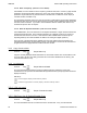
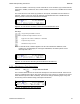
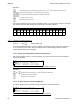
Table Of Contents
- OPERATING INSTRUCTIONS
- 1.1 Controls and Display
- 1.2 Transceiver Basic Operation
- 1.3 About Commands
- SECTION 2
- 2.1 Channel Operating Parameters
- 2.2 Editing Channel Operating Parameters
- 2.3 Scan and Multi-Mode Operation
- 2.4 Controlling User Access
- 2.5 Encrypted Operation
- 3.1 Operator Level 1 Commands
- 3.1.1 Select the Operating Memory for the Main Channel
- 3.1.2 Increase Display Brightness
- 3.1.3 Edit Channel Operating Mode
- 3.1.4 Scroll Backwards through Available Memories
- 3.1.5 Start/Stop Scan
- 3.1.6 Scroll Forewards through Available Memories
- 3.1.7 Edit Channel Operating Frequency
- 3.1.8 Decrease Display Brightness
- 3.1.9 Edit Channel Squelch Mode
- 3.1.10 Command Level Up
- 3.1.11 Toggle memory: current/home
- 3.1.12 Toggle Talk Around
- 3.1.13 Erase Encryption Keys
- 3.2 Operator Level 2 Commands
- 3.2.1 Create/Edit All Channel Information
- L2-1.1. Entering a Memory Number (refer to L1-1 for details)
- L2-1.2. Enter a Scan List & Enabling/Disabling Scan (refer to L2-5 for details)
- L2-1.3. Enter a Text Description (refer to L2-6 for details)
- L2-1.4. Enter an Operating Mode (refer to L1-3 for details)
- L2-1.5. Enter a Frequency (refer to L1-7 for details)
- L2-1.6. Enter the Squelch Parameters (refer to L1-9 for details)
- 3.2.2 Copy Guard to Main
- 3.2.3 Lock Keypad
- 3.2.4 L2-4 not used.
- 3.2.5 Edit Scan List & Enable/Disable Scan
- 3.2.6 Edit Memory Text Description
- 3.2.7 Create Shadow Memory
- 3.2.8 Copy Main to Guard
- 3.2.9 Encryption ON/OFF
- 3.2.10 Command Level Up
- 3.2.11 Command Level Down
- 3.2.12 L2–#. Not Used.
- 3.2.1 Create/Edit All Channel Information
- 3.3 Operator Level 3 Commands
- 3.3.1 Select Boot Channel
- 3.3.2 Assign Key by KeyTag
- 3.3.3 Set Numeric Edit Mode: Decimal or Hexadecimal
- 3.3.4 Display Firmware Release and Version Information
- 3.3.5 Edit Scan Parameters
- 3.3.6 Configure PTT Timer
- 3.3.7 Side Tone Audio Level Adjust
- 3.3.8 PC Data Upload/Download
- 3.3.9 Display Channel Squelch Parameters
- 3.3.10 Command Level Up
- 3.3.11 Command Level Down
- 3.3.12 Unused
- 3.4 Maintenance Commands (Level 4)
- 3.4.1 Set Default Record
- 3.4.2 Set Restricted Level Access Mode
- 3.4.3 Set Command Permissions
- 3.4.4 Set Memory Edit
- 3.4.5 L4-5. not used
- 3.4.6 L4-6. not used
- 3.4.7 Set Frequency Display
- 3.4.8 Assign KeyTags to Encryption Keys
- 3.4.9 Set Squelch Restrictions
- 3.4.10 Command Level Up
- 3.4.11 Command Level Down
- 3.4.12 L4-# not used
- 3.5 Supervisor Commands (Level 5)
- 4.1 Appendix A. Installing the Jumper for Restricted Level Access.
- 4.2 Appendix B. CTCSS Tone and DCS Code Tables
- 4.3 Appendix C. Programming Channel data using TDP and a PC.
- 4.4 Appendix C. 2.5 kHz & 6.25 kHz Valid Frequencies
- 4.5 Appendix D. Default Tables

08RE399 TDFM-136B Operating Instructions
L2-1.5. Enter a Frequency (refer to L1-7 for details)
After MODE, the cursor advances to the frequency parameter field, this is a seven (7) digit decimal
parameter, though the first digit is always one so the user cannot edit that digit. The frequency
parameter may be edited to any number between 136.0000 and 174.0000 in 2.5 kHz. steps. (ie
150.0025 is valid, 150.0046 is not).
This is a duplex parameter, that is, the user has a chance to edit both the receive value followed by
the transmit value. Once the receive value has been accepted, pressing 'ENTER' again will accept
the same value for transmit. If you wish to have a different value for transmit, then enter it now,
otherwise accept the value for simplex.
L2-1.6. Enter the Squelch Parameters (refer to L1-9 for details)
After FREQUENCY, the cursor advances to the Squelch Mode field. A single character field shows
the Squelch Mode selected. This is a duplex parameter so a different mode can be chosen for
transmit than was chosen for receive. Note that the modes available will be restricted by the
Operating Mode (ie the modes available are different for analog and digital operation).
Once the user is finished and selects ‘ENTER’ then the newly edited channel parameters are
selected and displayed for the appropriate channel. This may take a moment as the information is
programmed into the appropriate RF module at this time as well.
3.2.2 Copy Guard to Main
Level 2 Key Scope: Main only
Copy the currently displayed Guard information UP to the Main channel. This is irreversible, so be
sure you wish to do this. As a safety precaution this command is disabled from the factory. (see
Command Permissions L4-2).
3.2.3 Lock Keypad
Level 2 Key Scope: Main and Guard
This command locks the keypad to prevent accidental change to parameters of the radio
unbeknownst to the operator. This will disable all keyboard functions (except keyboard unlock and
display luminance).
Edit Keys
Lock the keypad, display 'locked' until key release.
Unlock the keypad (after 2 seconds), display 'unlocked' until key release.
3.2.4 L2-4 not used.
Level 2 Key Scope: Command unused.
3.2.5 Edit Scan List & Enable/Disable Scan
Level 2 Key Scope: Main only
This command allows the user to select which of the SCAN LISTs - if any - that the selected
36 Technisonic Industries Ltd