
User's Manual
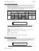
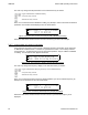
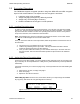
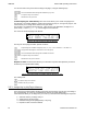
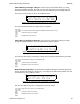
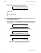
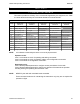
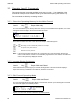
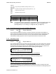
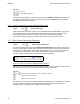
Table Of Contents
- OPERATING INSTRUCTIONS
- 1.1 Controls and Display
- 1.2 Transceiver Basic Operation
- 1.3 About Commands
- SECTION 2
- 2.1 Channel Operating Parameters
- 2.2 Editing Channel Operating Parameters
- 2.3 Scan and Multi-Mode Operation
- 2.4 Controlling User Access
- 2.5 Encrypted Operation
- 3.1 Operator Level 1 Commands
- 3.1.1 Select the Operating Memory for the Main Channel
- 3.1.2 Increase Display Brightness
- 3.1.3 Edit Channel Operating Mode
- 3.1.4 Scroll Backwards through Available Memories
- 3.1.5 Start/Stop Scan
- 3.1.6 Scroll Forewards through Available Memories
- 3.1.7 Edit Channel Operating Frequency
- 3.1.8 Decrease Display Brightness
- 3.1.9 Edit Channel Squelch Mode
- 3.1.10 Command Level Up
- 3.1.11 Toggle memory: current/home
- 3.1.12 Toggle Talk Around
- 3.1.13 Erase Encryption Keys
- 3.2 Operator Level 2 Commands
- 3.2.1 Create/Edit All Channel Information
- L2-1.1. Entering a Memory Number (refer to L1-1 for details)
- L2-1.2. Enter a Scan List & Enabling/Disabling Scan (refer to L2-5 for details)
- L2-1.3. Enter a Text Description (refer to L2-6 for details)
- L2-1.4. Enter an Operating Mode (refer to L1-3 for details)
- L2-1.5. Enter a Frequency (refer to L1-7 for details)
- L2-1.6. Enter the Squelch Parameters (refer to L1-9 for details)
- 3.2.2 Copy Guard to Main
- 3.2.3 Lock Keypad
- 3.2.4 L2-4 not used.
- 3.2.5 Edit Scan List & Enable/Disable Scan
- 3.2.6 Edit Memory Text Description
- 3.2.7 Create Shadow Memory
- 3.2.8 Copy Main to Guard
- 3.2.9 Encryption ON/OFF
- 3.2.10 Command Level Up
- 3.2.11 Command Level Down
- 3.2.12 L2–#. Not Used.
- 3.2.1 Create/Edit All Channel Information
- 3.3 Operator Level 3 Commands
- 3.3.1 Select Boot Channel
- 3.3.2 Assign Key by KeyTag
- 3.3.3 Set Numeric Edit Mode: Decimal or Hexadecimal
- 3.3.4 Display Firmware Release and Version Information
- 3.3.5 Edit Scan Parameters
- 3.3.6 Configure PTT Timer
- 3.3.7 Side Tone Audio Level Adjust
- 3.3.8 PC Data Upload/Download
- 3.3.9 Display Channel Squelch Parameters
- 3.3.10 Command Level Up
- 3.3.11 Command Level Down
- 3.3.12 Unused
- 3.4 Maintenance Commands (Level 4)
- 3.4.1 Set Default Record
- 3.4.2 Set Restricted Level Access Mode
- 3.4.3 Set Command Permissions
- 3.4.4 Set Memory Edit
- 3.4.5 L4-5. not used
- 3.4.6 L4-6. not used
- 3.4.7 Set Frequency Display
- 3.4.8 Assign KeyTags to Encryption Keys
- 3.4.9 Set Squelch Restrictions
- 3.4.10 Command Level Up
- 3.4.11 Command Level Down
- 3.4.12 L4-# not used
- 3.5 Supervisor Commands (Level 5)
- 4.1 Appendix A. Installing the Jumper for Restricted Level Access.
- 4.2 Appendix B. CTCSS Tone and DCS Code Tables
- 4.3 Appendix C. Programming Channel data using TDP and a PC.
- 4.4 Appendix C. 2.5 kHz & 6.25 kHz Valid Frequencies
- 4.5 Appendix D. Default Tables

TDFM-136B Operating Instructions 08RE399
Edit Keys
step up through available operating modes (w, n, D)
step down through available operating modes (w, n, D)
accept the entry and exit
abandon the entry and exit
Table 3-2 Transceiver Operating Modes
Operating Mode Bandwidth Indicator
Analog Wide 25 kHz
'w'
Analog Narrow 12.5 kHz
'n'
P25 Digital 12.5 kHz
'D'
Note: If an Operating Mode is selected that is incompatible with the current Squelch Mode, then
the Squelch mode will automatically be changed to one that is acceptable for that
Operating Mode (ie >x' for analog, 'm' for Digital Rx and 'g' for Digital Tx).
3.1.4 Scroll Backwards through Available Memories
Level 1 Key Scope: Main only
Press and hold the back arrow (4) key to scroll the memories for the Main Channel BACK, or
down, through the programmed memories until reaching the lowest memory programmed, it will
then wrap around and restart from the top. Once the user releases the button the displayed
characteristics will be programmed. The scroll speed will increase as the button is held.
3.1.5 Start/Stop Scan
Level 1 Key Scope: Main only
This command allows the user to start and stop Scan operation, the system will scan the channels
that are in the same scan list that the currently displayed Main channel is a member of. Note that
the channels in the scan list must have scan enabled (see command L2-5) to be scanned. If the
scan has not been enabled for the memory, then the following screen appears:
Figure 3-3. Trying to start scan on a Channel with Scan disabled
If the channel has been enabled for scan the user will see the following screen:
Figure 3-4. Start scan on a Channel with Scan enabled
Once scan has started the scan list digit flashes to indicate that the unit is in SCAN mode. Also
note that the key level indicator position has the lock symbol, this indicates that all keypad keys are
disabled except for:
Technisonic Industries Ltd. 29
KB
,"+ D
KB
4