
User's Manual
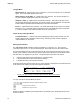
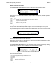
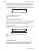
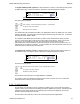
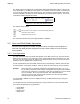
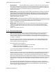
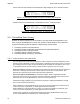
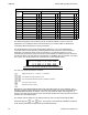
Table Of Contents
- OPERATING INSTRUCTIONS
- 1.1 Controls and Display
- 1.2 Transceiver Basic Operation
- 1.3 About Commands
- SECTION 2
- 2.1 Channel Operating Parameters
- 2.2 Editing Channel Operating Parameters
- 2.3 Scan and Multi-Mode Operation
- 2.4 Controlling User Access
- 2.5 Encrypted Operation
- 3.1 Operator Level 1 Commands
- 3.1.1 Select the Operating Memory for the Main Channel
- 3.1.2 Increase Display Brightness
- 3.1.3 Edit Channel Operating Mode
- 3.1.4 Scroll Backwards through Available Memories
- 3.1.5 Start/Stop Scan
- 3.1.6 Scroll Forewards through Available Memories
- 3.1.7 Edit Channel Operating Frequency
- 3.1.8 Decrease Display Brightness
- 3.1.9 Edit Channel Squelch Mode
- 3.1.10 Command Level Up
- 3.1.11 Toggle memory: current/home
- 3.1.12 Toggle Talk Around
- 3.1.13 Erase Encryption Keys
- 3.2 Operator Level 2 Commands
- 3.2.1 Create/Edit All Channel Information
- L2-1.1. Entering a Memory Number (refer to L1-1 for details)
- L2-1.2. Enter a Scan List & Enabling/Disabling Scan (refer to L2-5 for details)
- L2-1.3. Enter a Text Description (refer to L2-6 for details)
- L2-1.4. Enter an Operating Mode (refer to L1-3 for details)
- L2-1.5. Enter a Frequency (refer to L1-7 for details)
- L2-1.6. Enter the Squelch Parameters (refer to L1-9 for details)
- 3.2.2 Copy Guard to Main
- 3.2.3 Lock Keypad
- 3.2.4 L2-4 not used.
- 3.2.5 Edit Scan List & Enable/Disable Scan
- 3.2.6 Edit Memory Text Description
- 3.2.7 Create Shadow Memory
- 3.2.8 Copy Main to Guard
- 3.2.9 Encryption ON/OFF
- 3.2.10 Command Level Up
- 3.2.11 Command Level Down
- 3.2.12 L2–#. Not Used.
- 3.2.1 Create/Edit All Channel Information
- 3.3 Operator Level 3 Commands
- 3.3.1 Select Boot Channel
- 3.3.2 Assign Key by KeyTag
- 3.3.3 Set Numeric Edit Mode: Decimal or Hexadecimal
- 3.3.4 Display Firmware Release and Version Information
- 3.3.5 Edit Scan Parameters
- 3.3.6 Configure PTT Timer
- 3.3.7 Side Tone Audio Level Adjust
- 3.3.8 PC Data Upload/Download
- 3.3.9 Display Channel Squelch Parameters
- 3.3.10 Command Level Up
- 3.3.11 Command Level Down
- 3.3.12 Unused
- 3.4 Maintenance Commands (Level 4)
- 3.4.1 Set Default Record
- 3.4.2 Set Restricted Level Access Mode
- 3.4.3 Set Command Permissions
- 3.4.4 Set Memory Edit
- 3.4.5 L4-5. not used
- 3.4.6 L4-6. not used
- 3.4.7 Set Frequency Display
- 3.4.8 Assign KeyTags to Encryption Keys
- 3.4.9 Set Squelch Restrictions
- 3.4.10 Command Level Up
- 3.4.11 Command Level Down
- 3.4.12 L4-# not used
- 3.5 Supervisor Commands (Level 5)
- 4.1 Appendix A. Installing the Jumper for Restricted Level Access.
- 4.2 Appendix B. CTCSS Tone and DCS Code Tables
- 4.3 Appendix C. Programming Channel data using TDP and a PC.
- 4.4 Appendix C. 2.5 kHz & 6.25 kHz Valid Frequencies
- 4.5 Appendix D. Default Tables

08RE399 TDFM-136B Operating Instructions
Table 2-3. Permission Applicability by Command and Level
Cmnd
Num
Level 1 Level 2 Level 3
Command M G Command M G Command M G
1 Select Main Memory
●
●
Create/Prog All
●
●
Set Main Boot Memory
●
●
2 Display Brighter
●
●
Copy Guard to Main
●
●
Assign Key by KeyTag
●
●
3 Edit Operating Mode
●
●
Lock Keypad
●
●
Set Edit HEX/Decimal
●
●
4 Scroll Memory Down
●
●
not used X X Show Firmware Version
●
●
5 Scan
●
X Edit Scan List
●
X Set Scan Parameters
●
●
6 Scroll Memory Up
●
●
Edit Text
●
●
Set PTT Timer
●
●
7 Edit Frequency
●
●
Create Shadow
●
X Set sidetone level
●
●
8 Display Dimmer
●
●
Copy Main to Guard
●
●
Communicate with PC
●
●
9 Edit Squelch Mode
●
●
Encryption ON/OFF
●
●
Show Squelch
●
●
ENT Jump to Home Memory
●
X Set Home Memory
●
●
not used X X
The default configuration from the factory has all commands enabled, except L2-2 and L2-8.
Permissions are controlled via three screens that allow you to visually enable or disable each
command for Main and Guard on a level by level basis.
The Set Permissions screen shows the level being affected (L1, L2, or L3), followed by the
command number, and an optional 'g' indicating Guard channel operation for that command (if
applicable). The character directly under each number (or 'g') indicates whether or not the
command may be accessed. If the command is to be accessible (or enabled), then the character is
a is solid round dot, if the command is to be restricted, (or disabled), then the character is an empty
dot or donut. The ‘Set Permissions’ for command level 1 screen appears below:
Figure 2-19. The Screen to Edit the Level 1 Permissions
The user may edit the permissions as follows:
Toggle permission ( @ = enabled, A = disabled
step up/down through Operator Levels
move backward/forward through the available commands
accept the entry and exit
abandon the entry and exit
Note that the cursor will automatically jump to the next valid column, the cursor will wrap. The ‘g’
indicates a separate Guard option; for the commands that support this, the Main and Guard can be
enabled/disabled separately. In addition, some of the commands are either channel agnostic, or
specific to the Main channel only and can thus be invoked for Main even when the radio front panel
switches are in the Guard position.
For example: with the switches in the Guard position the user can still scroll through the Main
memories using the and keys. These types of commands are available in the Guard
mode, but the permissions are determined by the Main permission.
20 Technisonic Industries Ltd
-/1B40BC#B6
@@@@@@@@@@@@@