
User's Manual
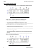
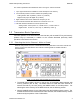
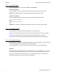
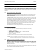
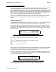
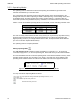
Table Of Contents
- OPERATING INSTRUCTIONS
- 1.1 Controls and Display
- 1.2 Transceiver Basic Operation
- 1.3 About Commands
- SECTION 2
- 2.1 Channel Operating Parameters
- 2.2 Editing Channel Operating Parameters
- 2.3 Scan and Multi-Mode Operation
- 2.4 Controlling User Access
- 2.5 Encrypted Operation
- 3.1 Operator Level 1 Commands
- 3.1.1 Select the Operating Memory for the Main Channel
- 3.1.2 Increase Display Brightness
- 3.1.3 Edit Channel Operating Mode
- 3.1.4 Scroll Backwards through Available Memories
- 3.1.5 Start/Stop Scan
- 3.1.6 Scroll Forewards through Available Memories
- 3.1.7 Edit Channel Operating Frequency
- 3.1.8 Decrease Display Brightness
- 3.1.9 Edit Channel Squelch Mode
- 3.1.10 Command Level Up
- 3.1.11 Toggle memory: current/home
- 3.1.12 Toggle Talk Around
- 3.1.13 Erase Encryption Keys
- 3.2 Operator Level 2 Commands
- 3.2.1 Create/Edit All Channel Information
- L2-1.1. Entering a Memory Number (refer to L1-1 for details)
- L2-1.2. Enter a Scan List & Enabling/Disabling Scan (refer to L2-5 for details)
- L2-1.3. Enter a Text Description (refer to L2-6 for details)
- L2-1.4. Enter an Operating Mode (refer to L1-3 for details)
- L2-1.5. Enter a Frequency (refer to L1-7 for details)
- L2-1.6. Enter the Squelch Parameters (refer to L1-9 for details)
- 3.2.2 Copy Guard to Main
- 3.2.3 Lock Keypad
- 3.2.4 L2-4 not used.
- 3.2.5 Edit Scan List & Enable/Disable Scan
- 3.2.6 Edit Memory Text Description
- 3.2.7 Create Shadow Memory
- 3.2.8 Copy Main to Guard
- 3.2.9 Encryption ON/OFF
- 3.2.10 Command Level Up
- 3.2.11 Command Level Down
- 3.2.12 L2–#. Not Used.
- 3.2.1 Create/Edit All Channel Information
- 3.3 Operator Level 3 Commands
- 3.3.1 Select Boot Channel
- 3.3.2 Assign Key by KeyTag
- 3.3.3 Set Numeric Edit Mode: Decimal or Hexadecimal
- 3.3.4 Display Firmware Release and Version Information
- 3.3.5 Edit Scan Parameters
- 3.3.6 Configure PTT Timer
- 3.3.7 Side Tone Audio Level Adjust
- 3.3.8 PC Data Upload/Download
- 3.3.9 Display Channel Squelch Parameters
- 3.3.10 Command Level Up
- 3.3.11 Command Level Down
- 3.3.12 Unused
- 3.4 Maintenance Commands (Level 4)
- 3.4.1 Set Default Record
- 3.4.2 Set Restricted Level Access Mode
- 3.4.3 Set Command Permissions
- 3.4.4 Set Memory Edit
- 3.4.5 L4-5. not used
- 3.4.6 L4-6. not used
- 3.4.7 Set Frequency Display
- 3.4.8 Assign KeyTags to Encryption Keys
- 3.4.9 Set Squelch Restrictions
- 3.4.10 Command Level Up
- 3.4.11 Command Level Down
- 3.4.12 L4-# not used
- 3.5 Supervisor Commands (Level 5)
- 4.1 Appendix A. Installing the Jumper for Restricted Level Access.
- 4.2 Appendix B. CTCSS Tone and DCS Code Tables
- 4.3 Appendix C. Programming Channel data using TDP and a PC.
- 4.4 Appendix C. 2.5 kHz & 6.25 kHz Valid Frequencies
- 4.5 Appendix D. Default Tables

08RE399 TDFM-136B Operating Instructions
2.2.2 Operating Modes
The operating mode is defined as the RF channel spacing and modulation type used for the
selected channel/memory on the transceiver.
The unit supports three operating modes: Analog wide, analog narrow, and P25 digital. In the
analog wide mode, the radio is operating on 25kHz. channel spacing, on both analog narrow, and
in P25 digital mode, the radio operates with 12.5kHz. channel spacing. In analog modes the
transceiver operates using standard frequency modulation, in the P25 mode the unit uses C4FM.
Table 2-1 shows the available Operating Modes, the bandwidth, and the indicating character used.
Table 2-1 Transceiver Operating Modes
Operating Mode Bandwidth Indicator
Analog Wide 25 kHz
'w'
Analog Narrow 12.5 kHz
'n'
P25 Digital 12.5 kHz
'D'
The user can easily switch between modes on any memory for any channel (ie any Main memory,
and both Guard1 and Guard2). Since the squelch modes are not common across analog and
digital operating modes, if you change between these modes, the Squelch Mode will be affected
(for more on this see 'Squelch Modes' below).
The operating mode is a simplex parameter.
Editing Operating Mode
The edit operating mode command is easily accessible, it is command L1-3. To access this
command, simply press '3', on the front panel keypad. Notice that the key is also marked “MODE”.
This command allows the user to edit the operating mode of the selected channel & memory. Since
operating mode is simplex only, the editor is very simple. Upon start, the cursor appears at the
operating mode character field of the channel to be edited. The edit screen appears as follows:
Figure 2-5. The user screen to edit the Main Operating Mode.
You may now edit the Operating Mode as follows:
step up/down through available operating modes (w, n, D)
accept the entry and exit
abandon the entry and exit
10 Technisonic Industries Ltd
!)*$%&'