
User's Manual
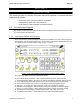
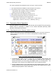
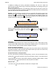
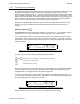
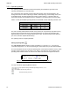
Table Of Contents
- OPERATING INSTRUCTIONS
- 1.1 Controls and Display
- 1.2 Transceiver Basic Operation
- 1.3 About Commands
- SECTION 2
- 2.1 Channel Operating Parameters
- 2.2 Editing Channel Operating Parameters
- 2.3 Scan and Multi-Mode Operation
- 2.4 Controlling User Access
- 2.5 Encrypted Operation
- 3.1 Operator Level 1 Commands
- 3.1.1 Select the Operating Memory for the Main Channel
- 3.1.2 Increase Display Brightness
- 3.1.3 Edit Channel Operating Mode
- 3.1.4 Scroll Backwards through Available Memories
- 3.1.5 Start/Stop Scan
- 3.1.6 Scroll Forewards through Available Memories
- 3.1.7 Edit Channel Operating Frequency
- 3.1.8 Decrease Display Brightness
- 3.1.9 Edit Channel Squelch Mode
- 3.1.10 Command Level Up
- 3.1.11 Toggle memory: current/home
- 3.1.12 Toggle Talk Around
- 3.1.13 Erase Encryption Keys
- 3.2 Operator Level 2 Commands
- 3.2.1 Create/Edit All Channel Information
- L2-1.1. Entering a Memory Number (refer to L1-1 for details)
- L2-1.2. Enter a Scan List & Enabling/Disabling Scan (refer to L2-5 for details)
- L2-1.3. Enter a Text Description (refer to L2-6 for details)
- L2-1.4. Enter an Operating Mode (refer to L1-3 for details)
- L2-1.5. Enter a Frequency (refer to L1-7 for details)
- L2-1.6. Enter the Squelch Parameters (refer to L1-9 for details)
- 3.2.2 Copy Guard to Main
- 3.2.3 Lock Keypad
- 3.2.4 L2-4 not used.
- 3.2.5 Edit Scan List & Enable/Disable Scan
- 3.2.6 Edit Memory Text Description
- 3.2.7 Create Shadow Memory
- 3.2.8 Copy Main to Guard
- 3.2.9 Encryption ON/OFF
- 3.2.10 Command Level Up
- 3.2.11 Command Level Down
- 3.2.12 L2–#. Not Used.
- 3.2.1 Create/Edit All Channel Information
- 3.3 Operator Level 3 Commands
- 3.3.1 Select Boot Channel
- 3.3.2 Assign Key by KeyTag
- 3.3.3 Set Numeric Edit Mode: Decimal or Hexadecimal
- 3.3.4 Display Firmware Release and Version Information
- 3.3.5 Edit Scan Parameters
- 3.3.6 Configure PTT Timer
- 3.3.7 Side Tone Audio Level Adjust
- 3.3.8 PC Data Upload/Download
- 3.3.9 Display Channel Squelch Parameters
- 3.3.10 Command Level Up
- 3.3.11 Command Level Down
- 3.3.12 Unused
- 3.4 Maintenance Commands (Level 4)
- 3.4.1 Set Default Record
- 3.4.2 Set Restricted Level Access Mode
- 3.4.3 Set Command Permissions
- 3.4.4 Set Memory Edit
- 3.4.5 L4-5. not used
- 3.4.6 L4-6. not used
- 3.4.7 Set Frequency Display
- 3.4.8 Assign KeyTags to Encryption Keys
- 3.4.9 Set Squelch Restrictions
- 3.4.10 Command Level Up
- 3.4.11 Command Level Down
- 3.4.12 L4-# not used
- 3.5 Supervisor Commands (Level 5)
- 4.1 Appendix A. Installing the Jumper for Restricted Level Access.
- 4.2 Appendix B. CTCSS Tone and DCS Code Tables
- 4.3 Appendix C. Programming Channel data using TDP and a PC.
- 4.4 Appendix C. 2.5 kHz & 6.25 kHz Valid Frequencies
- 4.5 Appendix D. Default Tables

TDFM-136B Operating Instructions 08RE399
The common parameters are identified as items 7 through 11 and are as follows:
7. Up to eight characters are available for a text description of the memory.
8. One character position is used to indicate the operating mode:
Analog modes: wide "w"(25kHz.), narrow "n" (12.5kHz.)
Digital mode: project 25 digital "D" (12.5kHz.).
9. Eight characters are used to indicate the frequency in use.
10. One character indicates either Receive or Transmit as: "R" or "T".
11. The final character indicates the current squelch mode:
Analog modes: noise squelch "x", CTCSS tones "t", or DCS codes "c"
Digital modes: monitor "m", NAC only "n", TalkGroup + NAC "g"
1.2 Transceiver Basic Operation
For basic operation of the transceiver the user has the yolk mounted PTT key and memory
up/down keys (if connected) in addition to the controls discussed previously. Basic
operation is discussed in this section.
1.2.1 Selecting the Active Channel – Main or Guard
When the user presses 'PTT', the unit will transmit with the parameters of the active channel and
memory, that the user has selected. The method of selecting MAIN or GUARD channel is
described below.
Figure 1-4. The active channel display and control points.
1. The MAIN channel data is shown on the top line of the display, MAIN supports 230
memory positions (001 to 230). The MAIN channel is made the active channel for
transmit and edit by the user placing the MN/GD switch in the MN position. For
selecting the active memory for the MAIN channel, see the following section.
2. When the MN/GD switch is in the GD position then the GUARD channel is active. The
GUARD channel has two fixed memories: GD1 and GD2, the GUARD memory used is
determined by the position of the G1/G2 switch.
Technisonic Industries Ltd. 3