
User's Manual


TECHNISONIC INDUSTRIES LIMITED
www.til.ca
TDFM-136A Installation Instructions Page A-1
TiL 09RE404 Rev C Issue 1
APPENDIX A – POST INSTALLATION EMI TEST INSTRUCTIONS”
PURPOSE
The purpose of these tests is to identify any interference that the TDFM-136A may cause with
existing aircraft systems.
TEST CONDITIONS
The TDFM-136A transceiver should be installed and function tested. The antenna VSWR should
be checked. A forward/reverse power check with an in-line wattmeter should show no more than
10% reflected power. For the following tests, insure that the power switch is in the high position.
METHODOLOGY
Most of the EMI tests can be accomplished on the ground. In some cases flight testing is required
or is easier. If the aircraft is approved for IFR operations, then it is mandatory that interference
between the TDFM-136A Airborne FM and the approach aids be checked in flight.
The GPS should be operational and navigating with at least the minimum compliment of
satellites. The VHF COMM should be set to the frequencies indicated with the squelch open.
VOR/DME receivers should be set to the frequencies indicated and selected for display. If
possible, set up a DME ramp test set on the frequencies indicated and adjust the output until the
flags are out of view. The transponder and encoder should be monitored with ramp test
equipment. Set the output of the transponder test set to 3db above the output necessary to
achieve 90% reply. If possible set the ADF to a nearby navigation station.
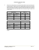
Modulate the TDFM-136A transmitter on the indicated frequencies for at least 20 seconds.
Observe the GPS for any degradation in satellite status or availability or flags. Listen for any
noise or detected audio signals on the VHF COMM(s). Listen for any noise or detected audio
signals on the VOR/LOC receiver audio; look for any movement of flags or needles on the
VOR/LOC/GS navigation display(s). Observe the transponder for any loss of reply or spurious
reply.
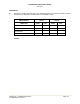
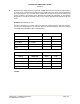
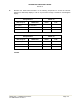
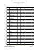
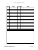
List the power plant, fuel and other electric instruments in the chart provided and note any
anomalies that occur while transmitting. Assess the results.
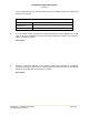
If the aircraft is equipped with an auto-pilot or a stability augmentation system, then test fly the
aircraft and verify that operation of the TDFM-136A transceiver does not have adverse effects on
these systems. After checking for gross effects at a safe altitude, fly an approach with each of the
different navigation systems coupled to the auto-pilot (ILS, GPS etc.) and look for any anomalies.
RESULTS
If the installed system passes all of the applicable EMI tests, then no further action is required. If
interference is observed, then the interference must be assessed against the appropriate
standards of airworthiness for the system in question. For example, it is permissible for a VFR
certified GPS to lose navigation capability while the TDFM-136A is transmitting providing that it
recovers properly and promptly, but is not permissible for an IFR approach certified GPS to be
affected in the same way. A complete discussion of all the standards of airworthiness to be
applied in assessing EMI effects is beyond the scope of this document.