
User's Manual

TECHNISONIC INDUSTRIES LIMITED
www.til.ca
TDFM-136A Operating Instructions Page 2-30
TiL 09RE405
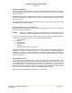
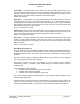
The basic operation of the TDFM-136A radio is accomplished through the front panel user
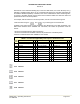
interface. The front panel layout is shown in figure 2-41 below.
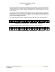
FIGURE 2-41 The TDFM-136A Front Panel Layout
The front panel comprises the following:
A) LED display, two line x 24 character F) Toggle switch (two position: G1/G2)
B) Rotary volume control (with on/off switch) G) Toggle switch (two position: HI/LO)
C) Rotary volume control H) Keypad, twelve button (numbers 0-9, # and *)
D) Push button switch (momentary contact) I) Keyloader
E) Toggle switch (two position: MN/GD)
A The display provides two lines of text information—in the normal operating mode, the top
line provides information about the Main channel, the bottom line information about the
selected Guard channel.
B & C The rotary potentiometers control the audio level for each of the Main and Guard
channels respectively. The Main volume control also contains the radio power switch.
D The single pushbutton provides the squelch defeat function and opens the squelch in
analog modes, and sets the receive squelch to accept all in digital modes (though this will
not open the squelch unless there is a valid P25 digital signal present).
E, F The three toggle switches allow the user to select:
& G Main and Guard channels, Guard 1 or Guard 2 channel, and High or Low RF power.
Note that the channel select switches (MN/GD and G1/G2) will control which channel is
active for any channel editing command (see Sections 2.1 through 2.5).
H The 12 button keypad allows the user access to the system commands including
commands for selecting channels, editing channel parameters, and for system
configuration.
I Keyloader (for future use).
PTT keying is provided via the back connector, and is part of a correctly installed system.