
User's Manual

TECHNISONIC INDUSTRIES LIMITED
www.til.ca
TDFM-136A Operating Instructions Page 2-1
TiL 09RE405
SECTION 2 – OPERATING INSTRUCTIONS
This section provides the user with a reference of the keypad accessible programming features of the
Technisonic TDFM-136A VHF/FM Digital Transceiver.
This section is divided into subsections as follows:
2.1 command structure overview and terms
2.2, 2.3, 2.4 and 2.5 detailed command descriptions by level
2.6 detailed operating description
2.1 COMMAND METHODOLOGY
This section describes how the TDFM-136A command structure is organized.
Command Levels
In order to accommodate the necessary commands, the commands have been divided into
different levels, each command level has up to 12 commands numbered 0-9, # and *; the zero
(0), and the ESC (*) key are functions for every level, they allow the user to move between levels
as follows:
step up through command levels
step down through command levels
When stepping through command levels, the indicated level is shown in subscript in the 4th
character position on the lower line of the display. Note that this display position is left blank for
the default level (level1). Table 2-1 shows the command levels and the associated display
character.
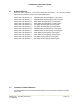
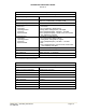
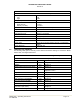
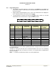
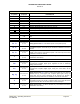
Table 2 Command Levels
COMMAND LEVEL DISPLAY
Command/Operator L1 blank
Command/Operator L2
2
Command/Operator L3
3
Command/Maintenance L4
4
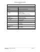
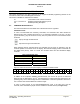
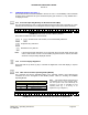
Figure 2-1 below shows the front panel display for different Command levels.
0 0 1 M a i n D 1 3 4 . 0 0 0 0 R g
G D 2
3
G u a r d 2 w 1 7 4 0 0 0 0 R t
FIGURE 2-1 User Screen showing the Command Level Display Position
In addition to the 3-operator available command levels, the unit can be put into a mode that
allows access for Maintenance. This 4
th
command level (L4) allows authorized personnel to set
operating policy for the radio through the use of 'Permissions'. These are explained in section 2-8.
This command level should NEVER be enabled in flight.
In order to restrict access to the Command/Maintenance Level 4, the side cover must be
removed, and a maintenance jumper must be installed on the MCU board (see Figure 2-33).