T6 ANALOG MULTIBAND RF MODULE Installation and Operating Instructions TiL Document No. 22RE638 Revision B OCTOBER 2022 Technisonic Industries Limited 240 Traders Boulevard, Mississauga, Ontario L4Z 1W7 Tel: (905) 890-2113 Fax: (905) 890-5338 www.til.ca Copyright by Technisonic Industries Limited. All rights reserved.
NOTES CAUTION STATIC SENSITIVE ! This unit contains static sensitive devices. Wear a grounded wrist strap and/or conductive gloves when handling printed circuit boards. FCC COMPLIANCE INFORMATION This device complies with Part 15 of the FCC Rules. Operation is subject to the following two conditions: (1) this device may not cause harmful interference and (2) this device must accept any interference received, including interference that may cause undesired operation.
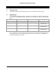
TECHNISONIC INDUSTRIES LIMITED TABLE OF CONTENTS SECTION TITLE PAGE 1 1.1 1.2 GENERAL DESCRIPTION B INTRODUCTION ............................................................................................................. 1 DESCRIPTION ................................................................................................................ 1 2 2.1 2.2 2.3 2.4 2.5 2.6 2.7 2.8 2.9 2.10 2.11 OPERATING INSTRUCTIONS B GENERAL ........................................................................
TECHNISONIC INDUSTRIES LIMITED SECTION 1: GENERAL DESCRIPTION 1.1 INTRODUCTION This publication provides operating information for the T6 multiband transceiver module. 1.2 DESCRIPTION The T6 multiband transceiver module is designed to be installed in an airborne multiband radio such as one of the TDFM-9000 series transceivers.
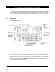
TECHNISONIC INDUSTRIES LIMITED SECTION 2: OPERATING INSTRUCTIONS 2.1 GENERAL An LED display, a keypad, and a rotary knob provide the operator control of RF modules installed in the unit. The T6 module will always be band 3. The display shows the activity of the selected module as well as the soft key menu of the active band. The active module is selected by pressing the BAND key. The knob has multiple functions including volume, channel, and zone. 2.
TECHNISONIC INDUSTRIES LIMITED 2.4 KNOB The knob is a rotary encoder, which turns endlessly. The knob also has a push button incorporated so you can press the knob as well. Pressing the knob will toggle through the following possible knob modes: Volume Channel Zone NumLock Recall Band 3 (T6 module) only supports volume and channel knob modes. The current function of the knob is shown at the bottom right of the display. Some of these modes can be enabled or disabled in the Configuration Menu.
TECHNISONIC INDUSTRIES LIMITED 2.9 DISPLAY The transceiver has a three line 72 character LED display. The zone name, channel name, condition symbols (scan, direct, call, secure, monitor, etc.), and switch settings will be displayed for each module. The active band is indicated by a pointer on the left side of the display. The bottom line displays the menu items associated with the module selected and the mode of the knob. 2.
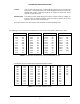
TECHNISONIC INDUSTRIES LIMITED TX DCS VHF LO and UHF bands only. TX DCS will only appear if the TX CTCSS was set to ‘OFF.’ The transmit DCS code will be displayed. Rotate the knob to the desired code or ‘OFF.’ Selecting off will set the channel to carrier only. Press the knob or ‘Next’ menu key. Channel Name The Channel name will be displayed. Edit the channel name by rotating the knob to select the desired character. Press the knob to advance to the next character. The name is 9 characters long.
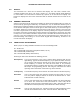
TECHNISONIC INDUSTRIES LIMITED SECTION 3: INSTALLATION INSTRUCTIONS 3.1 GENERAL The T6 Module is designed to be installed in a Technisonic airborne radio chassis as an option for extended frequency coverage. These radio chassis include, but are not limited to Technisonic transceiver models TDFM-9100, TDFM-9200 and TDFM-9300. A TDFM-9100 installation is shown below. The others are very similar. The T6 is intended to be mounted in the TDFM 9300/9200 or 9100 chassis and is not visible.
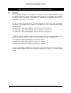
TECHNISONIC INDUSTRIES LIMITED 3.2 INSTALL INTERFACE BOARD The interface board is only required in the TDFM-9100 Transceiver. Remove top cover and install interface board assembly 203085. Install 6 screws with lock washers.
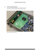
TECHNISONIC INDUSTRIES LIMITED 3.3 INSTALL T6 MODULE Fit module into top tray position ensuring proper header connection. Install 4 screws holding the module tray. Install 6 hex head screws into the heat sink block. Connect the antenna coax as shown above. Install new top cover #218212. 3.4 FINAL ALIGNMENT AND TEST Perform final alignment procedure for appropriate transceiver model. Perform final test procedure for appropriate transceiver model.
TECHNISONIC INDUSTRIES LIMITED SECTION 4: SPECIFICATIONS 4.1 SPECIFICATIONS Specification Characteristic RF Output Power: 1 or 10 Watts (VLO) 1 or 4.5 Watts (VHF) 1 or 4.5 Watts (UHF) Frequency Range VHF low Band: VHF Band: UHF Band: 30 - 50 MHz (FM) 108 – 117.975 MHz (AM receive only) 117.975 – 136.975 MHz (AM) 225 – 399.975 MHz (AM) No.