
User's Manual


3-3
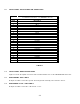
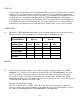
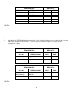
3.6 INSTALLATION - PIN LOCATIONS AND CONNECTIONS
J1 - 25 Pin D Connections - Use FEMALE Connector
Pin #
Description
1 Ground
2 Main Power +28 VDC
3 Mic 1
4 Audio 1
5 PTT 1
6 Mic 2
7 Audio 2
8 PTT 2
9 Mic 3
10 Audio 3
11 PTT 3
12 TX Data
13 RX Data
14 Ground
15 Main Power +28 VDC
16 Channel Up
17 Channel Down
18 LH Data
19 SB9600 Busy
20 OPTB+
21 CTS Out
22 Boot DIN
23 RTSBIN
24 RS232DIN
25 Panel Backlighting
TABLE 3-1
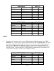
3.7 INSTALLATION - WIRING INSTRUCTIONS
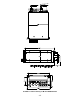
Figure 3-2 shows all required connections and recommended wire sizes for the TDFM-600/6000 transceiver.
3.8 MAIN GROUND - PINS 1 AND 14
Both pins should be connected to ground. The main ground is internally connected to the chassis.
3.9 MAIN POWER +28 VDC - PINS 2 AND 15
Both pins should be connected to +28 volts DC +/- 15%.