
User's Manual

TECHNISONIC INDUSTRIES LIMITED
www.til.ca
TMS-100 90-6R/8.33
Installation & Operating Instructions
TiL 02RE301 Rev B
3-3
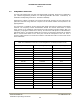
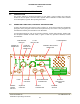
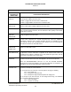
TABLE 3.1 OPERATORS SWITCHES, CONTROLS AND INDICATORS
SWITCHES,
CONTROLS &
INDICATORS
FUNCTIONAL DESCRIPTION
POWER ON/OFF
SWITCH
A two-position toggle switch which controls the application of the 12/24 volts
nominal power supply to the transceiver.
Position 1, toggle UP, the transceiver is switched ON.
Position 0, toggle DOWN, the transceiver is switched OFF.
POWER ON LED
INDICATOR
A green LED which is ON when the POWER ON/OFF switch is set to Position 1,
and the vehicle power supply is applied to the transceiver.
FUSE A 5-ampere fuse which protects the 12/24 volts nominal power supply line. As
part of reverse polarity protection, the fuse will "blow" when polarity of the vehicle
supply line is reversed.
FUSE BLOWN
RED LED
INDICATOR
A red LED which is ON when the 5-ampere fuse is "blown", and the vehicle power
supply is applied to the transceiver.
SQUELCH
CONTROL
A linear potentiometer, which is operative when the transceiver is operated in the
receive mode, determines the squelch threshold level. When the SQUELCH
CONTROL is adjusted in the counter-clockwise direction, the SQUELCH green
LED indicator will go ON, indicating that the squelch circuit is connecting the
demodulated audio to the VOLUME control.
SQUELCH
INDICATOR
GREEN LED
A green LED which is ON when the squelch circuit is connecting the demodulated
audio to the VOLUME control.
TX ON YELLOW
LED INDICATOR
A yellow LED which is ON when the microphone PRESS-TO-TALK (PTT) switch
is depressed, and the transceiver is operated in the transmit mode. When the
microphone PTT switch is released, the Tx ON yellow LED goes OFF, and the
transceiver is operated in the receive mode.
VOLUME
CONTROL
A logarithmic potentiometer, which is operative when the transceiver is in the
receive mode, determines the audio level applied to the internal loudspeaker.
When the SPEAKER/PHONE connector is in use the VOLUME CONTROL
determines the audio level applied to the external loudspeaker or headphone, as
appropriate, and the internal loudspeaker is disconnected.
MIC/PTT
CONNECTOR
A 5-pin connector which performs two functions, one as the microphone/PTT
connector, secondly as a test connector.
(1) It accepts the 3-pin connector of the microphone carrying the following:
Pin 1 - PTT Signal Line
Pin 2 - Microphone Signal Ground
Pin 3 - Microphone Signal and Microphone DC Supply Line
(2) It accepts a 5-pin test connector, for use during bench testing. The additional
pins provide the following test points:
Pin 4 - AGC test voltage
Pin 5 - Squelch test voltage