
User's Manual

TECHNISONIC INDUSTRIES LIMITED
www.til.ca
TMS-100 90-6R/8.33
Installation & Operating Instructions
TiL 02RE301 Rev B
3-1
SECTION 3 – OPERATING INSTRUCTIONS
3.1 INTRODUCTION
This section includes a functional description of each switch, control, indicator and connector
located on the front panel of the transceiver, together with the PRESS-TO-TALK switch included
on the microphone, together with operating instructions.
3.2 OPERATOR'S SWITCHES, CONTROLS AND INDICATORS
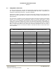
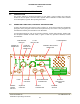
A view of the transceiver front panel is given in Figure 3.1. Front panel controls are identified by
pictograms. Each pictogram shows the function performed by the control. These pictograms are
translated into words by the annotations of the illustration.
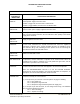
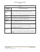
A functional description of each of the operator's switches, controls and indicators, together with
the microphone PRESS-TO-TALK switch, is given in Table 3.1, Operator's Switches, Controls
and Indicators.
FUSE BLOWN
RED LED
TX ON
YELLOW LED
LOUDSPEAKER
POWER ON
GREEN LED
SQUELCH
INDICATOR
GREEN LED
CHANNEL INDICATORS
GREEN LED
FUSE
VOLUME
CONTROL
SPEAKER/PHONE
CONNECTOR
CHANNEL
DESIGNATION
LABEL
POWER
ON/OFF
SWITCH
SQUELCH
CONTROL
MIC/PTT
CONNECTOR
CHANNEL
SWITCH