
User's Manual


TECHNISONIC INDUSTRIES LIMITED
www.til.ca
TMS-100 90-6R/8.33
Installation & Operating Instructions
TiL 02RE301 Rev B
2-6
2.15 MICROPHONE INSTALLATION
Refer to Figure 1.4 for a general view of the microphone and retaining bracket. Determine a
suitable and convenient location for Retaining Bracket and secure it using appropriate hardware
(not provided). Connect the connector of Microphone, Part Number 961070-1 to the MIC/PTT
connector located on the front panel of the transceiver.
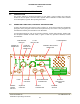
2.16 OPTIONAL EXTERNAL LOUDSPEAKER OR HEADPHONE
Provision is made for connection of either an external loudspeaker or headphone to the
SPEAKER/PHONE jack of the transceiver, as shown in Figure 4.1.
2.16.1 EXTERNAL LOUDSPEAKER
When an external loudspeaker is to be installed, an 8-ohm nominal impedance loudspeaker
should be used. The loudspeaker cable should be terminated by a 1/4 in., 3-pole telephone plug
(male), with the loudspeaker connected between tip and sleeve (ground). The External
loudspeaker connector should be connected to the SPEAKER/PHONE jack located on the front
panel of the transceiver. When the external loudspeaker connector is connected to the
transceiver SPEAKER/PHONE jack, the internal loudspeaker is automatically disconnected.
2.16.2 HEADSET
When a headset is to be used, the headset impedance should be 150 to 600-ohms. The headset
cable must be terminated by a 1/4in., 3-pole telephone plug (male), which mates with the
SPEAKER/PHONE jack located on the front panel of the transceiver. When connected, the
internal loudspeaker is automatically disconnected. The headset may be connected as detailed in
(1) for receiver audio with no transmit sidetone audio, or (2) for receiver audio with transmit
sidetone audio.
(1) HEADSET WITH NO TRANSMIT SIDETONE AUDIO
When receiver audio only with no transmit sidetone audio is required, the headset should be
connected between the tip and sleeve (ground) of the telephone plug.
(2) HEADSET WITH SIDETONE AUDIO
When receiver audio with transmit sidetone is required, the headset should be connected
between the tip and sleeve (ground) with a resistor (located inside the plug) connected between
the tip and ring of the telephone plug. The function of the resistor is to reduce the transmit
sidetone audio level to a suitable listening level. The value of the resistor is determined by the
headset impedance and desired listening level. When a 600-ohm impedance headset is used, the
value of the resistor should be approximately 10 kilohms. For headsets with lower impedance the
resistor value may be different but must not be less than 240-ohms.
2.17 OPERATIONAL CHECK
Perform an operational check of the transceiver, checking each channel in use in both the
transmit and receive modes of operation, using the Operating instructions given in Section 3 of
this document and the appropriate specified operating procedures during transmission.