
User's Manual

TECHNISONIC INDUSTRIES LIMITED
www.til.ca
TMS-100 90-6R/8.33
Installation & Operating Instructions
TiL 02RE301 Rev B
2-5
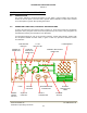
2.10 POWER INPUT CABLE ASSEMBLY
Using Power Input Cable Assembly, Part Number 863701, as shown in Figure 1.3, route the
unterminated end of the cable from the transceiver location to the point of connection to the fused
vehicle power supply. The three-metre cable may be cut to length as required. Coiling of excess
cable is NOT recommended. Strip the outer covering from the end of the cable, prepare the
individual wire ends, and fit suitable terminals. Connect the red wire to the positive supply (fused),
and connect the black wire to the negative supply ground.
2.11 ANTENNA ASSEMBLY
Antenna Assembly, Part Number 861910-1, is supplied as a kit which includes an installation
leaflet. The antenna is shown assembled in Figure 1.5.
2.12.1 ANTENNA LOCATION
The antenna location is a very important factor in determining the performance of the system. The
antenna may be mounted on any flat surface, roof, cowl, fender or rear deck of the vehicle,
however, rooftop mounting is recommended for best performance.
2.12.2 ANTENNA INSTALLATION
Having determined the location of the antenna, route the unterminated end of the antenna RF
cable from the transceiver location. Using the antenna installation leaflet, follow the step-by-step
instructions, and install the antenna. Any excess length of antenna RF cable should be cut-off
before connection to the antenna.
2.13 MOUNTING BRACKET INSTALLATION
Mounting Bracket, Part Number 913053-1, should be installed in the transceiver location using
Qty 4 Screws, Self-Tapping, Hex Hd with slot and shoulder No. 12 x3/4in. included in Mounting
Hardware Kit, Part Number 869024-1. Refer to Figure 1.2 for a view of the transceiver with
mounting bracket.
Using the mounting bracket as a template; on the mounting surface, mark the centre of each of
the four slotted mounting holes, and drill a pilot hole using a No. 19 drill or equivalent (actual pilot
hole size depends on the thickness of metal of mounting surface). Locate mounting bracket in
position, and secure using the screws provided.
2.14 TRANSCEIVER INSTALLATION
Locate the transceiver in its approximate position, connect the antenna connector, and power
cable connector to the appropriate connectors located at the rear of the transceiver.
Locate the transceiver into mounting bracket, and screw to bracket using two wing screws and
nylon washers included in Mounting Hardware Kit, Part Number 869024-1. Adjust angle of
transceiver as required, before tightening the two wing screws.